SF3-DC60V Просмотр технического описания (PDF) - Matsushita Electric Works
Номер в каталоге
Компоненты Описание
производитель
SF3-DC60V
Matsushita Electric Works

SF3-DC60V Datasheet PDF : 7 Pages
| |||
SAFETY STRUCTURE OF SF RELAYS
This SF relay design ensures that
externally caused circuit or device
subsequent operations shut down and can breakdowns, end of life incidents, and
automatically return to a safe state when noise, surge, and environmental
the SF relay suffers overloading and other influences) owing to contact welding,
circuit abnormalities (unforeseen
spring fusion or, in the worst-case
SF
scenario, relay breakdown (coil rupture,
faulty operation, faulty return, and fatigue
and breakage of the operating spring and
return spring), and even in the event of
end of life.
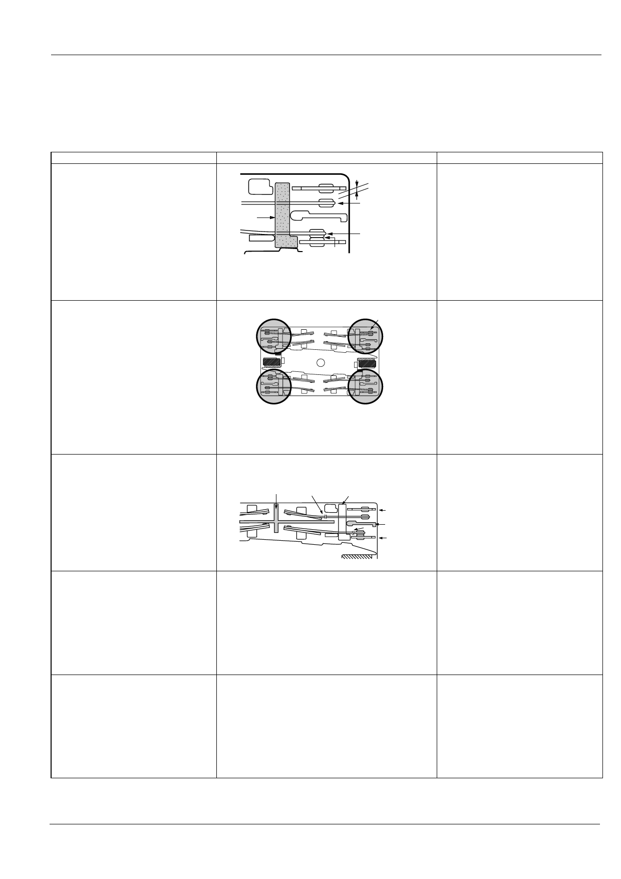
1. Forced operation method
(2a2b, 3a1b, 4a4b types)
Structure
Min. 0.5 mm .020 inch
Card
Contact a
Contact b
Weld
The two contacts “a” and “b” are coupled with the same
card. The operation of each contact is regulated by the
movement of the other contact.
Operation
Even when one contact is welded closed,
the other maintains a gap of greater than
0.5 mm .020 inch.
In the diagram on the left, the lower
contact "b" have welded but the upper con-
tact "a" maintain at a gap of greater than
0.5 mm .020 inch.
Subsequent contact movement is
suspended and the weld can be detected
2. Independent operation method
(4a4b type)
3. Separate chamber method
(2a2b, 3a1b, 4a4b types)
Return
External NO
contact weld
Enables design of safety circuits that allow
weld detection and return at an early stage.
Return
Return
None of four contacts are held in position by the armature.
Even though one of the external N.O. contacts has
welded, the other three contacts have returned owing to
the de-energizing of the coil.
As shown at the top right of the diagram on
the left, if the external N.O. contact welds, a
0.5 mm .020 inch gap is maintained.
Each of the other contacts returns to N.O.
because the coil is no longer energized.
In independent chambers, the contacts "a" and "b" are
kept apart by a body/card separator or by the card itself.
Case separator
1
Card
Prevents shorting and fusing of springs and
spring failure owing to short-circuit current.
Contact a
Body
2
separator
Contact b
As shown on the diagram on the left, even
if the operating springs numbered 1 and 2
there is no shorting between "a" and "b"
contacts.
4. High-efficiency 4-gap balanced
armature structure
(2a2b, 3a1b, 4a4b types)
The use of high-efficiency magnetically polarized circuits Does away with return faults due to fatigue
and 4-gap balanced armature structure means that
or breakage of the return spring, especially
springs are not required.
stoppage during contact states.
5. 2a2b contact
3a1b contact
4a4b contact
Structure with independent COM contact of (2a2b),
(3a1b), (4a4b) contacts.
Independent COM enables differing pole
circuit configurations. This makes it
possible to design various kinds of control
circuits and safety circuits.
261
Share Link: