MT90710 Просмотр технического описания (PDF) - Mitel Networks
Номер в каталоге
Компоненты Описание
производитель
MT90710 Datasheet PDF : 12 Pages
| |||
MT90710
Preliminary Information
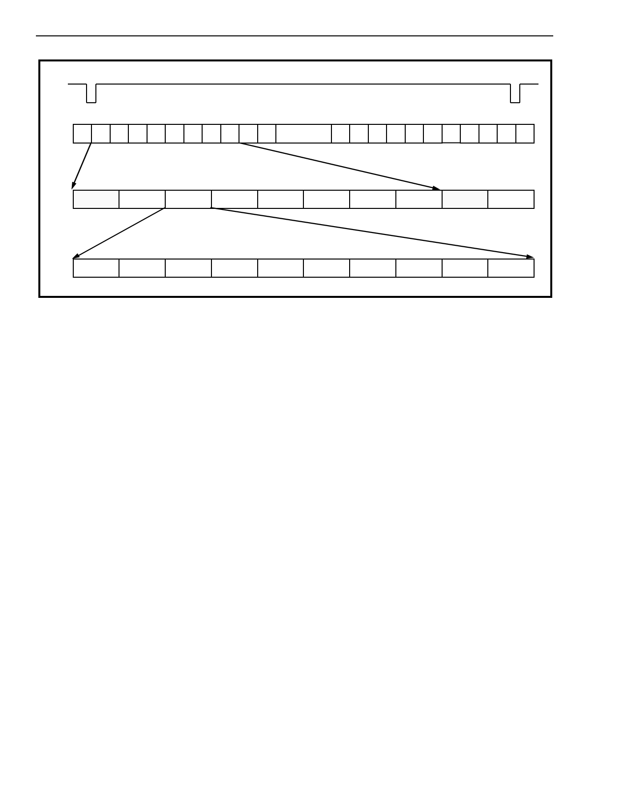
Frame Pulse
255 0 1 2 3 4
Fiber Timeslot
5 6789
..........
246 247 248 249 250 251 252 2
Channel Assignment
ST7 Ch0 ST6 Ch0 ST5 Ch0 ST4 Ch0 ST3 Ch0 ST2 Ch0 ST1 Ch0 ST0 Ch0 ST7 Ch1 ST6 Ch1
Bit 9 Bit 8
Bit 7
4B/5B Encoded Data Bit Assignment
Bit 6
Bit 5
Bit 4
Bit 3
Bit 2
Bit 1
Bit 0
Figure 3 - Fiber Timeslot Assignment
The MT90710 provides 15.808 Mb/s clear channel,
user bandwidth in both transmit and receive
directions. In addition, two 8 kHz sampled signals
and one 32 kHz sampled signal are encoded and
transported over the loop as additional user
bandwidth. These asynchronous signals, in
combination with overhead information and clear
channel bandwidth produce an aggregate data rate
of 16.384 Mb/s. After encoding (4B/5B) the final
transmitted baud rate is 20.48 Mbaud.
Once compiled, the contents of the transmit data
bandwidth is first 4B/5B encoded, then NRZI
encoded before it is applied to the transmit fiber
interface driver via TxDATA. 4B/5B ensures that the
NRZI encoded data will contain a minimum of two
transitions per baud. This is sufficient to allow the far
end to extract the embedded clock information. As a
result of 4B/5B encoding the information bandwidth
of 16.384 Mb/s increases to a total baud rate of
20.48 MBaud/s at the fiber interface.
Transmit
The transmit data interface consists of nine ST-BUS
input links and three asynchronously sampled input
signals. These are STi0 - STi5, STi6A and STi6B,
STi7, DIN8K0, DIN8K1 and DIN32K. Six ST-BUS
input links, STi0-5, each provide 2.048 Mb/s
transparent transmission bandwidth. With ST6MUX
Mode disabled STi6A is also a 2.048 Mb/s link while
STi6B is not used (see ST6MUX description). The
first nine channels of the STi7 input are ignored
leaving the remaining 23 channels for user
bandwidth. This allows a total of 15.808 Mb/s clear
bandwidth for application use. The first nine (576
kb/s) channels of STi7 are made available for
transmitting the three asynchronous signals
combined with fiber overhead information. This
overhead is automatically compiled in the transmit
interface and inserted into these timeslots for
transmission over the fiber interface.
Incoming ST-BUS link data is latched at the mid-bit
position of the internal timeslot. Since there is a
phase difference between the internal and external
timeslots, due to the operation of the PLL, latching
occurs at approximately the 3/4 bit position of the
external timeslot when in Controller mode. In
Peripheral mode data is latched at the midpoint of
the timeslot. Asynchronous signals DIN8K0-1 are
sampled once per frame (8,000 times per second)
and are intended to convey relatively static
information where a state transition is not time
critical enough that a resolution of one frame is
detrimental. Asynchronous signal DIN32K is
sampled four times per frame (32,000 times per
second) and may be used to transport data at a
higher rate than the other two asynchronous inputs.
As an example, this sampling rate is sufficient to
support 19.2K Baud RS-232 signals (TTL levels) so
that remote programming or loop maintenance may
be performed.
Overhead information includes a frame
synchronization byte, an error count and a checksum
calculated on the previous frame of transmitted data.
5-8
Share Link: 