M-993 Просмотр технического описания (PDF) - Clare Inc => IXYS
Номер в каталоге
Компоненты Описание
производитель
M-993 Datasheet PDF : 6 Pages
| |||
Pin Function
Pin
CE
D0 - D3
D4-D5
MUTE
OUTDRIVE
VDD
VREF
VSS
XIN
XOUT
Function
Latches data and enables output (active low
input).
Data input pins. (See Data/Tone Selection.)
Leave open.
Output indicates that a signal is being
generated at OUTDRIVE.
Linear buffered tone output.
Most positive power supply input pin.
Internally generated mid-power supply
voltage (output).
Most negative power supply input pin.
Crystal oscillator or digital clock input.
Crystal oscillator output.
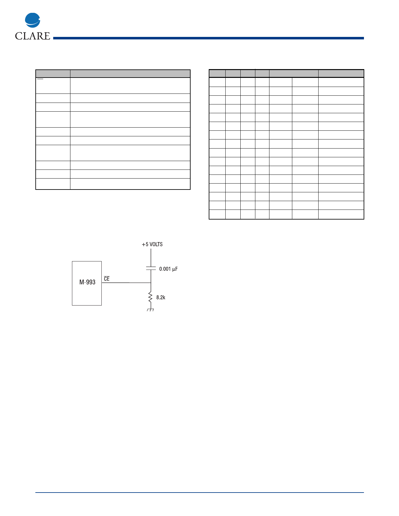
Power-On Reset Circuit
M-993
Data/Tone Selection
D3 D2 D1 D0 Frequency (Hz)
1
2
0 0 0 0 1100
1700
0 0 0 1 700
900
0 0 1 0 700
1100
0 0 1 1 900
1100
0 1 0 0 700
1300
0 1 0 1 900
1300
0 1 1 0 1100
1300
0 1 1 1 700
1500
1 0 0 0 900
1500
1 0 0 1 1100
1500
1 0 1 0 1300
1500
1 0 1 1 1500
1700
1 1 0 0 900
1700
1 1 0 1 1300
1700
1 1 1 0 700
1700
Use
Key Pulse (KP)
Digit 1
Digit 2
Digit 3
Digit 4
Digit 5
Digit 6
Digit 7
Digit 8
Digit 9
Digit 0
ST
ST1
ST2
ST3
A typical control sequence for the M-993 is: (1) set
data lines Selection for data settings for a particular
tone pair output).to desired frequency selection, (2)
wait for data lines to settle, (3) drive the chip enable
(CE) low, (4) maintain CE low for desired tone duration
(Note: data lines may be changed after data hold
time), and (5) return CE to a logic high.
In a bus-oriented system, noise on the data lines may
propagate through the device and appear at the out-
put. To safeguard against this, use an external latch to
clock the data into the device. In addition, it is good
practice to bypass the VREF pin to ground with a small
capacitor (~0.01mF) to reduce power supply noise.
The designer should be aware of device timing
requirements and design accordingly. Beware of hard-
wiring the data input pins for dedicated tone genera-
tion. An RC network like that shown in Power-On
Reset Circuit should be used to momentarily reset the
device immediately following a power-up to ensure
reliable operation.
Rev. 1
www.clare.com
3
Share Link: 