DS12887 Просмотр технического описания (PDF) - Dallas Semiconductor -> Maxim Integrated
Номер в каталоге
Компоненты Описание
производитель
DS12887 Datasheet PDF : 19 Pages
| |||
A. Periodic Interrupt Enable (PEI) bit is cleared to 0.
B. Alarm Interrupt Enable (AIE) bit is cleared to 0.
C. Update Ended Interrupt Flag (UF) bit is cleared to 0.
D. Interrupt Request Status Flag (IRQF) bit is cleared to 0.
E. Periodic Interrupt Flag (PF) bit is cleared to 0.
F. The device is not accessible until RESET is returned high.
G. Alarm Interrupt Flag (AF) bit is cleared to 0.
H. IRQ pin is in the high impedance state.
I. Square Wave Output Enable ( SQWE ) bit is cleared to 0.
J. Update Ended Interrupt Enable (UIE) is cleared to 0.
DS12887
In a typical application RESET can be connected to VCC. This connection will allow the DS12887 to go in
and out of power fail without affecting any of the control registers.
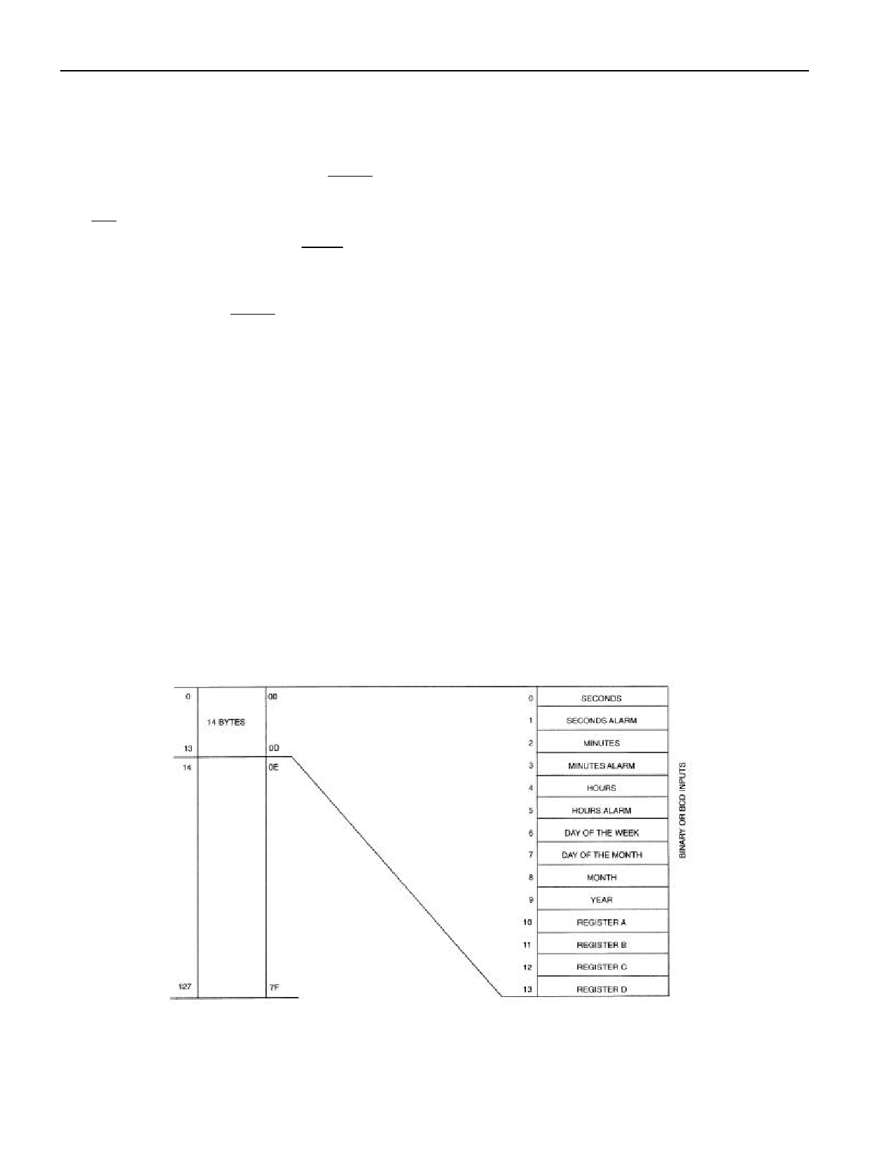
ADDRESS MAP
The address map of the DS12887 is shown in Figure 2. The address map consists of 114 bytes of user
RAM, 10 bytes of RAM that contain the RTC time, calendar, and alarm data, and 4 bytes which are used
for control and status. All 128 bytes can be directly written or read except for the following:
1. Registers C and D are read–only.
2. Bit 7 of Register A is read–only.
3. The high order bit of the seconds byte is read–only.
The contents of four registers (A,B,C, and D) are described in the “Registers” section.
ADDRESS MAP DS12887 Figure 2
5 of 19
Share Link: 