UT1750AR12WCC Просмотр технического описания (PDF) - Aeroflex UTMC
Номер в каталоге
Компоненты Описание
производитель
UT1750AR12WCC Datasheet PDF : 56 Pages
| |||
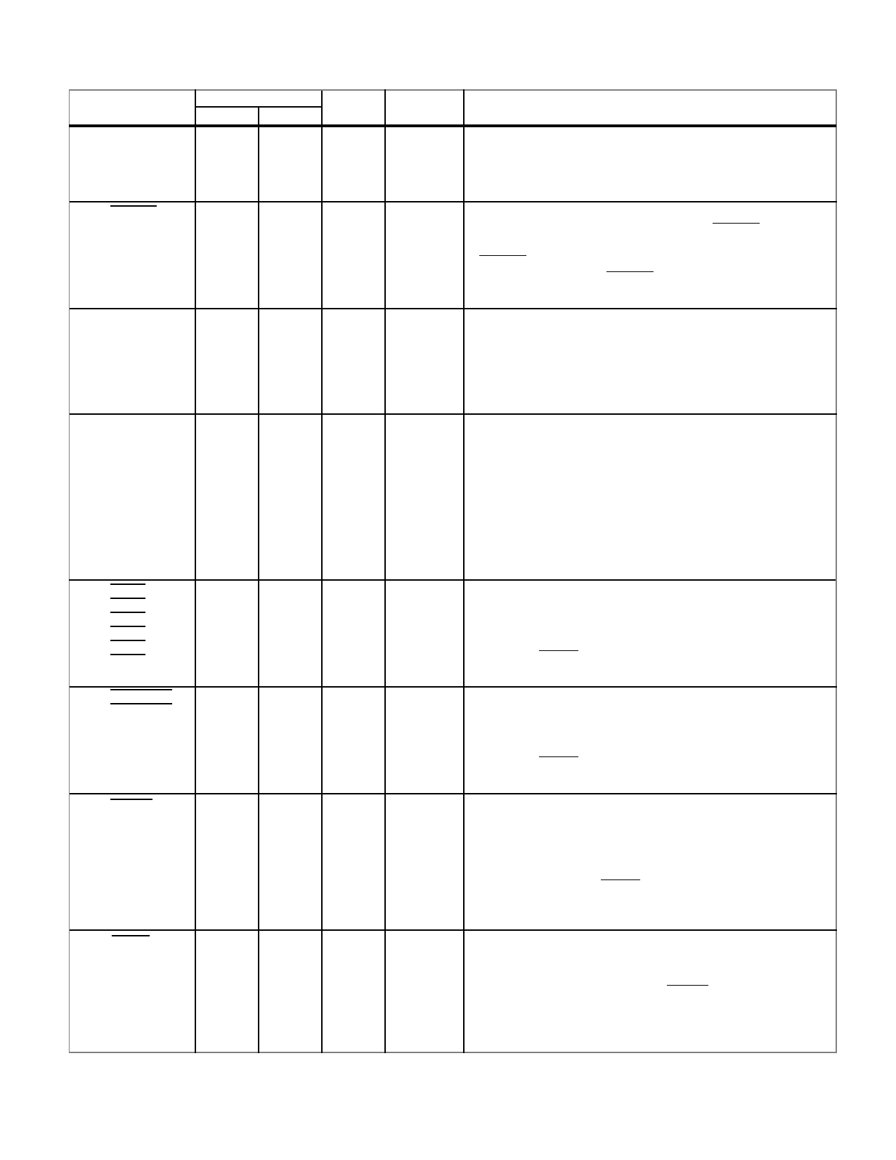
INTERRUPTS/EXCEPTIONS
PIN NAME
SYSFLT
BTERR
MPAR
MPROT
INT0
INT1
INT2
INT3
INT4
INT5
IOLINT0
IOLINT1
PFAIL
PIN NUMBER
FLTPK PGA
125
G2
122
D1
124
F2
123
F3
TYPE
TUI
TUI
TDI
TUI
ACTIVE
--
AL
AH
AH
DESCRIPTION
System Fault. This positive edge-triggered input sets bit 8
(SYSFLT) in the UT1750AR’s Fault Register. Under no
circumstances should SYSFLT be tied in its active state. It
is tied to an internal pull-up resistor.
Bus Time Error. It is asserted when a bus error or a timeout
occurs. During I/O bus cycles, an active BTERR sets bit 10
of the Fault Register. During Memory bus cycles, an active
BTERR sets bit 7 of the Fault Register. Under no
circumstances should BTERR be tied in its active state. It is
tied to an internal pull-up resistor.
Memory Parity (Error). Asserting this input indicates a
MIL-STD-1750 memory parity error. Bit 13 of the
UT1750AR’s Fault Register, Memory Parity Fault, is set
when MPAR is active. Under no circumstances should
MPAR be tied in its active state. It is tied to an internal
pull-down resistor.
Memory Protect Fault. When asserted, it informs the
UT1750AR that a memory-protect fault has occurred on the
Operand Data Bus. An access fault, a write-protect fault, or an
execute-protect fault causes a memory-protect fault. If the
UT1750AR is using the bus and MPROT is asserted, bit 15 of
the Fault Register (CPU Fault) is set. If the UT1750AR is not
using the bus and MPROT is asserted, bit 14 of the Fault
Register (DMA Error) is set. It is tied to an internal pull-up
resistor.
56
M15 TUI
57
K13
58
K14
59
J14
60
J13
61
K15
62
J15 TUI
63
H14
55
L14 TUI
--
User Interrupts. These interrupts are active on a negative-
going edge and each will set, when active, its associated bit
in the Pending Interrupt Register. The interrupts are maskable
by setting the associated bits in the Interrupt Mask Register.
Asserting MRST resets all interrupts. They are tied to an
internal pull-up resistor.
--
I/O Level Interrupts. These inputs are active on a negative-
going edge and each sets, when active, its associated bit in
the Pending Interrupt Register. The interrupts are maskable
by setting the associated bits in the Interrupt Mask Register.
Asserting MRST resets all interrupts. They are tied to an
internal pull-up resistor.
AL
Power Fail (Interrupt). Asserting this input informs the
UT1750AR that a power failure has occurred and the present
process will be interrupted. This input sets bit 15 in the Pending
Interrupt Register. A Power Fail Interrupt (bit 15) cannot be
disabled. When operating in the RISC mode, the UT1750AR
must be reset after a PFAIL to assure normal operation. It is
tied to an internal pull-up resistor.
MRST
47
R14 TUI
AL
Master Reset. This input initializes the UT1750AR to a
reset state. The UT1750AR must be reset after power
(Vcc) is within specification and stable to ensure proper
operation. The system must hold MRST active for at least
one period of SYSCLK to assure the UT1750AR will be
reset. It is tied to an internal pull-up resistor.
8
Share Link: 