UT1750AR12WCC Просмотр технического описания (PDF) - Aeroflex UTMC
Номер в каталоге
Компоненты Описание
производитель
UT1750AR12WCC Datasheet PDF : 56 Pages
| |||
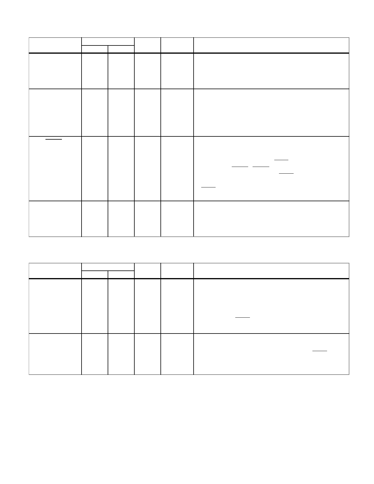
UART CONTROL/TIMER CLOCK
Continued from page 6
PIN NAME
TIMCLK
CONSOLE
TEST
PIN NUMBER
FLTPK PGA
53
L13
48
N12
46
P13
TYPE
TI
TDI
TUI
ACTIVE
--
AH
AL
DESCRIPTION
Timer Clock. This 12 MHz clock input generates the baud
rate for the UT1750AR’s internal UART. The input also
provides the clock for the UT1750AR’s two internal MIL-
STD-1750A timers (TIMER A and TIMER B).
Console (Command). Asserting this input sets bit 3 in the
System Status Register. Bit 3 is read with the Input Register
Instruction (INR). When the UT1750AR is operating in the
MIL-STD-1750 mode, asserting CONSOLE during a
Master Reset invokes the maintenance console option. Tied
to an internal pull-down resistor.
Test (Input). Asserting this input places the UT1750AR
into a test mode. In this mode, all the UT1750AR’s
outputs, except OSCOUT and SYSCLK, enter a high-
impedance state. When using TEST, the UT1750AR
must have a MRST. MRST must be held active for at
least one SYSCLK period after TEST is
deasserted to assure proper operation (see figure 42b).
TEST is tied to an internal pull-up resistor.
MME
49
N13 TDI
AH
Memory Management Enable. This signal indicates to
the UT1750AR that a Memory Management Unit
(MMU) is present and that the memory management
option is enabled. MME is tied to an internal pull-down
resistor.
PROCESSOR MODE
PIN NAME
AS0
AS1
AS2
AS3
PS0
PS1
PS2
PS3
PIN NUMBER
FLTPK PGA
104
B7
105
B6
106
C6
107
A5
108
A4
109
A3
110
B4
111
C5
TYPE
TTO
TTO
ACTIVE
AH
AH
DESCRIPTION
Address State. These outputs indicate the current address
state of the UT1750AR. Using these outputs with a
Memory Management Unit (MMU) allows selecting the
MMU’s page register group. These outputs enter a
high-impedance state when the UT1750AR is placed in
the test mode (TEST=0) or during bus cycles not assigned
to this processor.
Processor State. These outputs indicate the current state
of the processor. These outputs enter a high-impedance
state when the UT1750AR is in the test mode (TEST=0)
or during bus cycles not assigned to this processor.
7
Share Link: 