UT1750AR12WCC Просмотр технического описания (PDF) - Aeroflex UTMC
Номер в каталоге
Компоненты Описание
производитель
UT1750AR12WCC Datasheet PDF : 56 Pages
| |||
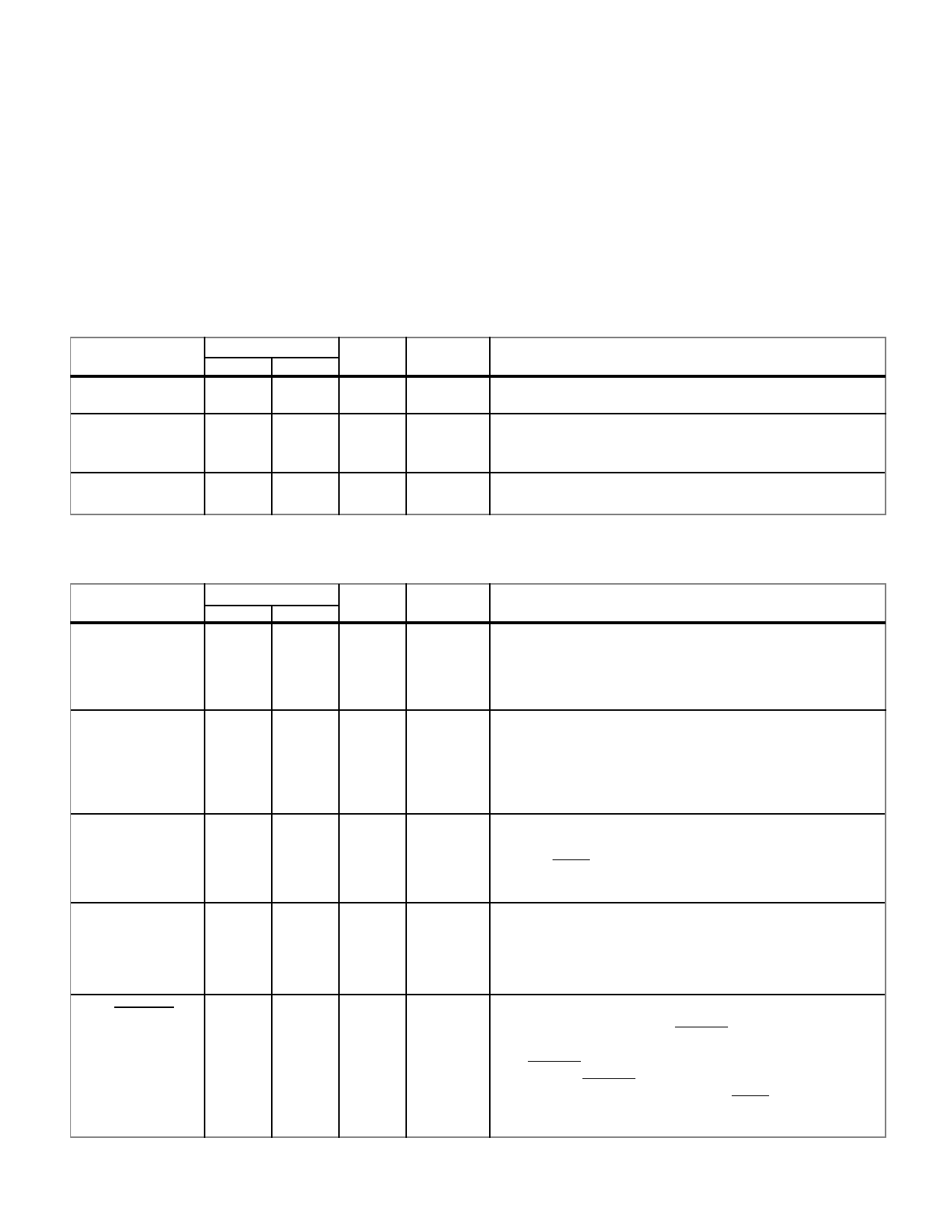
FUNCTIONAL PINOUT
Legend for TYPE and ACTIVE fields:
TO = TTL output
TI = TTL input
TUI = TTL input (pull-up)
TDI = TTL input (pull-down)
TTO = Three-state TTL output
TTB = Three-state TTL bidirectional
CO = CMOS output
OSC = Oscillator input to a Pierce Oscillator inverter
AH = Active High
AL = Active Low
OSCILLATOR AND CLOCK SIGNALS
PIN NAME
OSCIN
OSCOUT
PIN NUMBER
FLTPK PGA
50
P14
TYPE
OSC
ACTIVE
--
DESCRIPTION
Oscillator Input. A 50% duty cycle crystal-drive input for
51
P15
CO
--
Oscillator Output. A 50% duty cycle, single-phase clock
output at the same frequency as the OSCIN input.
SYSCLK
52
M14
TO
--
System Output. The buffered equivalent of the OSCOUT
PROCESSOR STATUS
PIN NAME
NUI1
PIN NUMBER
FLTPK PGA
129
H2
TYPE ACTIVE
TI
AH
DESCRIPTION
Not used input 1. Internal UTMC use only. Tie either high
NUI2
44
P12
TUI
AL
Not used input 2. Internal UTMC use only. Tie low.
NUO3
M1750
STATE1
4
126
G3
TTO
AH
Not used output 3. Internal UTMC use only. NUO3 enter
high impedance state when the UT1750AR is in the test
mode (TEST=0)
45
N11 TDI
AH
Mode Select RISC/1750. A high on M1750 places the
UT1750AR into the MIL-STD-1750A emulation mode.
A low on M1750 places the UT1750AR into the RISC
mode. It is tied to an internal pull-down resistor.
54
N15 TTO
--
Processor State. This signal indicates the internal state of
the UT1750AR. A low on STATE1 indicates the
UT1750AR is executing a new RISC instruction. A high
on STATE1 indicates the UT1750AR is fetching a RISC
instruction. STATE1 enters a high-impedance state when
the UT1750AR is in the test mode (TEST=0).
Share Link: 