UT1750AR12WCC Просмотр технического описания (PDF) - Aeroflex UTMC
Номер в каталоге
Компоненты Описание
производитель
UT1750AR12WCC Datasheet PDF : 56 Pages
| |||
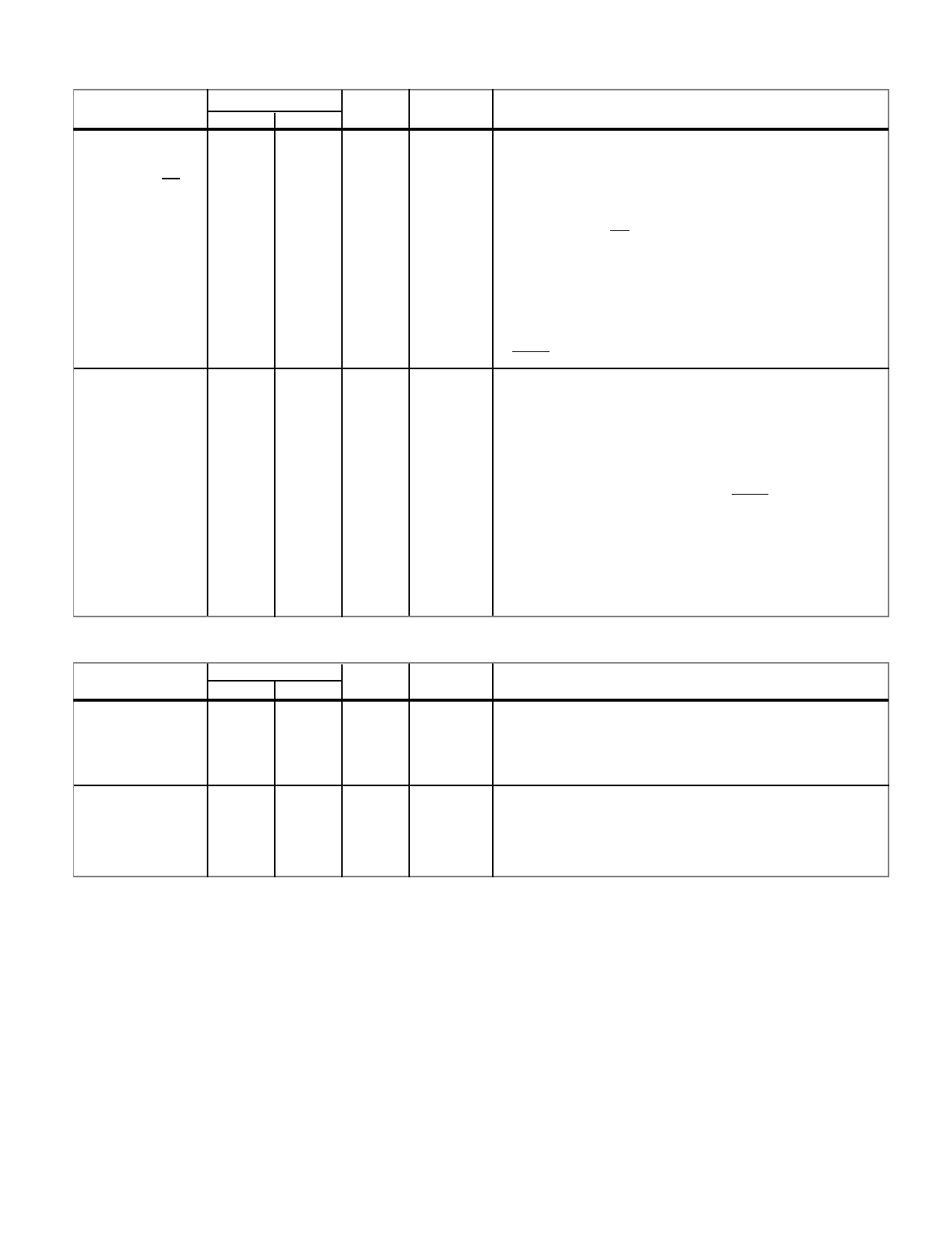
RISC BUSSES
Continued from page 9.
PIN NAME
RA16/OD3
RA17/OD2
RA18/OD1
RA19/CS
RD0
RD1
RD2
RD3
RD4
RD5
RD6
RD7
RD8
RD9
RD10
RD11
RD12
RD13
RD14
RD15
PIN NUMBER
FLTPK PGA
38
P9
39
P10
40
N10
41
R11
130
H1
3
J1
4
K1
5
J2
6
K2
7
K3
8
L1
9
M1
10
N1
11
M2
12
L3
13
N2
14
P1
15
M3
16
N3
17
P2
TYPE
TTO
TTB
ACTIVE
AH
AH
DESCRIPTION
RISC Instruction Address Bus/Output Discretes. When the
UT1750AR is operating in the RISC mode (M1750 = 0)
these four bits represent the four most significant address
bits. In the MIL- STD-1750A mode (M1750 = 1) these four
bits are user-programmable output discretes defined as
follows:
RA19/CS = Chip Select (AL)
RA18/OD1 = Output Discrete 1
RA17/OD2 = Output Discrete 2
RA16/OD3 = Output Discrete 3
These output discretes are programmed with the Output
Register (OTR) RISC opcode. These signals enter a high-
impedance state when the UT1750AR is in the test mode
(TEST = 0).
RISC Instruction Data Bus. This bidirectional data bus is
the interface with the RISC memory. When the
UT1750AR is in the MIL-STD-1750A mode of
operation, the data comes from the emulation ROMs.
This data is executed to emulate the MIL-STD-1750A
Instruction Set. RD15 is the most significant bit. The
RISC Data Bus enters a high-impedance state only when
the UT1750AR is in the test mode (TEST = 0).
POWER AND GROUND
PIN NAME
VDD
PIN NUMBER
FLTPK PGA
34
H3
67
N9
100
G13
132
C7
TYPE
--
ACTIVE
--
DESCRIPTION
+5 VDC Power. Power supply input.
VSS
1
J3
--
--
Reference Ground. Zero VDC logic ground.
33
N8
66
H13
99
C8
10
Share Link: 