ADM9264ARN-REEL Просмотр технического описания (PDF) - Analog Devices
Номер в каталоге
Компоненты Описание
производитель
ADM9264ARN-REEL Datasheet PDF : 12 Pages
| |||
ADM9264
APPLICATIONS
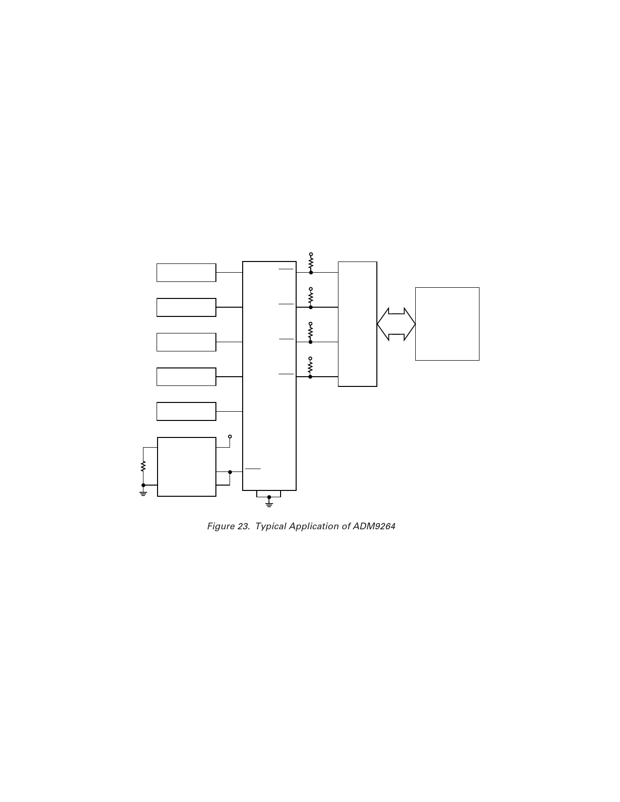
A typical application of the ADM9264 is shown in Figure 23.
The analog inputs SU1 to SU4 are connected to the four power
supply outputs of a system to monitor the supply voltages.
One of the digital inputs, ERRY, is connected to a temperature
sensor such as the TMP01 or AD22105. The trip point of the
overtemperature comparator is set by RSET so that the output
goes low when the temperature exceeds safe limits. (See the
appropriate Analog Devices data sheet for more information on
these devices.)
The other digital input, ERRX, is connected to a fan failure
sensor. This can be something as simple as a vane switch
mounted in the fan air flow, which opens if the air flow fails.
The digital outputs of the ADM9264 are interfaced to the
system microprocessor through the GPIO lines or via an I/O
adapter chip. Depending on the level of fault diagnostics
required in the system, the four error outputs (ERR1 to ERR4)
corresponding to the analog inputs SU1 to SU4 can be indi-
vidually connected to the I/O chip to give specific indication of
which supply voltage has failed, while the PWROK output
indicates an overtemperature or system cooling failure. Alter-
natively, the PWROK output can be used alone to give a
nonspecific failure indication.
PSU #1
12V
PSU #2
5V
PSU #3
3.3V
PSU #4
2.8V
SU1
SU2
SU3
SU4
VCC
ERR1
10kΩ
VCC
ERR2
10kΩ
VCC
ERR3
10kΩ
VCC
ERR4
10kΩ
SUPER I/O
CHIP
MICROPROCESSOR
RSET
FAN
(ALARM MONITOR)
ERRX
6
7
AD22105
TEMPERATURE
SENSOR 1
3
2
VCC
ADM9264
ERRY
DIS SU4DET
Figure 23. Typical Application of ADM9264
–10–
REV. 0
Share Link: 