ESDA14V2-4BF1 Просмотр технического описания (PDF) - STMicroelectronics
Номер в каталоге
Компоненты Описание
производитель
ESDA14V2-4BF1 Datasheet PDF : 9 Pages
| |||
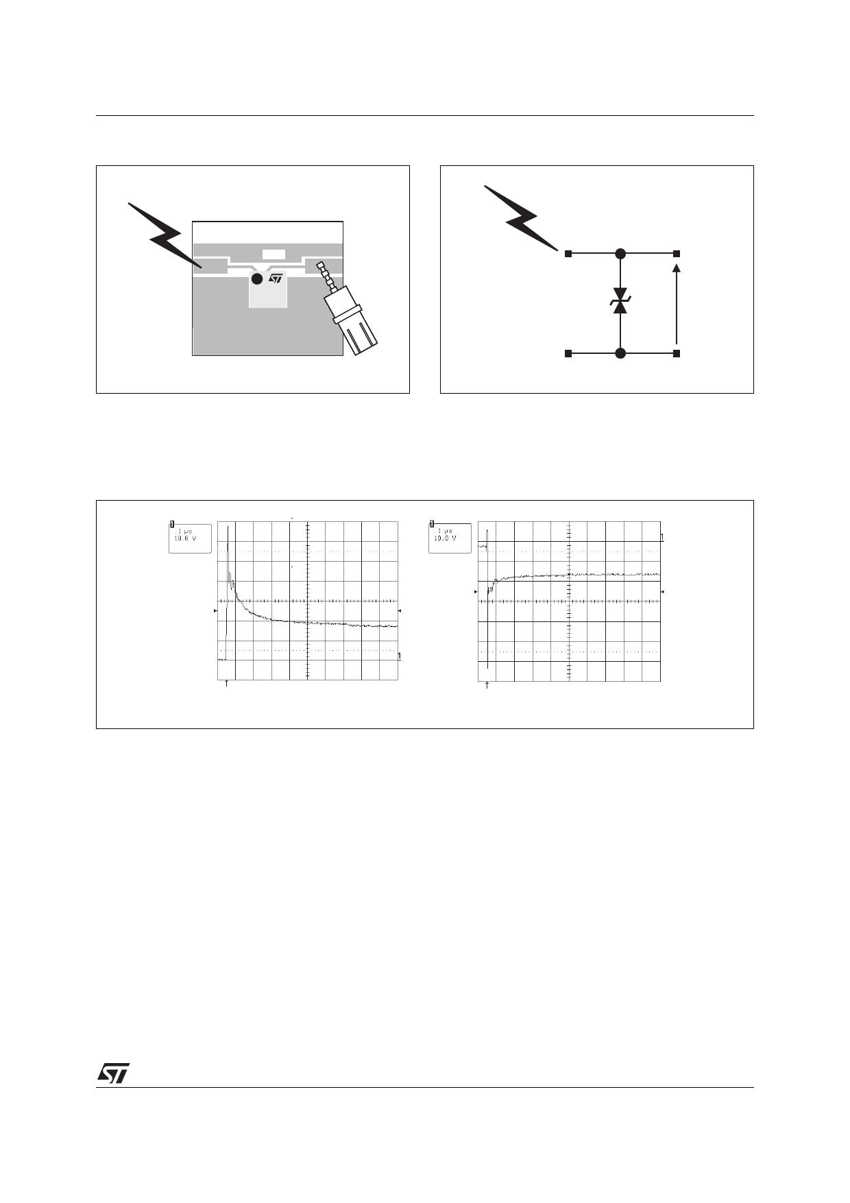
Fig. A2: ESD test board.
ESDA14V2-4BF1
Fig. A3: ESD test condition.
TEST BOARD
V(i/o)
®
EB14
15
A1, C1, A3 or C3
± 15kV
ESD Air discharge
V(i/o)
B2
The measurements done here after show very clearly (figure A4) the high efficiency of the ESD protection:
the clamping voltage V(i/o) becomes very close to VBR (positive way, figure A4a) and -VBR (negative way,
figure A4b).
Fig. A4: Remaining voltage during ESD surge.
V(i/o)
V(i/o)
a: Response in the positive way
b: Response in the negative way
5/9
®
Share Link: 