BA3842 Просмотр технического описания (PDF) - ROHM Semiconductor
Номер в каталоге
Компоненты Описание
производитель
BA3842 Datasheet PDF : 13 Pages
| |||
Audio ICs
FCircuit operation
(1) Operating power supply voltage range
Within the operating power supply voltage range, circuit
functioning is guaranteed as long as the operating tem-
perature range is not exceeded. However, verify carefully
that the voltage, temperature, and component values are
appropriate.
(2) Control pins and control voltage settings
(1) The DC control range is 0 V to VCC for the preset
equalizer and the dynamic bass boost control pins (pins
18 and 19). Make sure that the voltage applied to these
control pins does not exceed VCC.
(2) Mode switch threshold values are determined by di-
viding resistors between VCC and GND of both the preset
equalizer and bass boost. If the control voltages are di-
vided from the supply voltage of the IC, they will have
greater tolerance with respect to VCC fluctuations.
(3) During mode switching, an abrupt change in the level
of the DC output may occur, causing a sound. In this
case, add the capacitor and resistor indicated in the ap-
plication, or only the capacitor as needed.
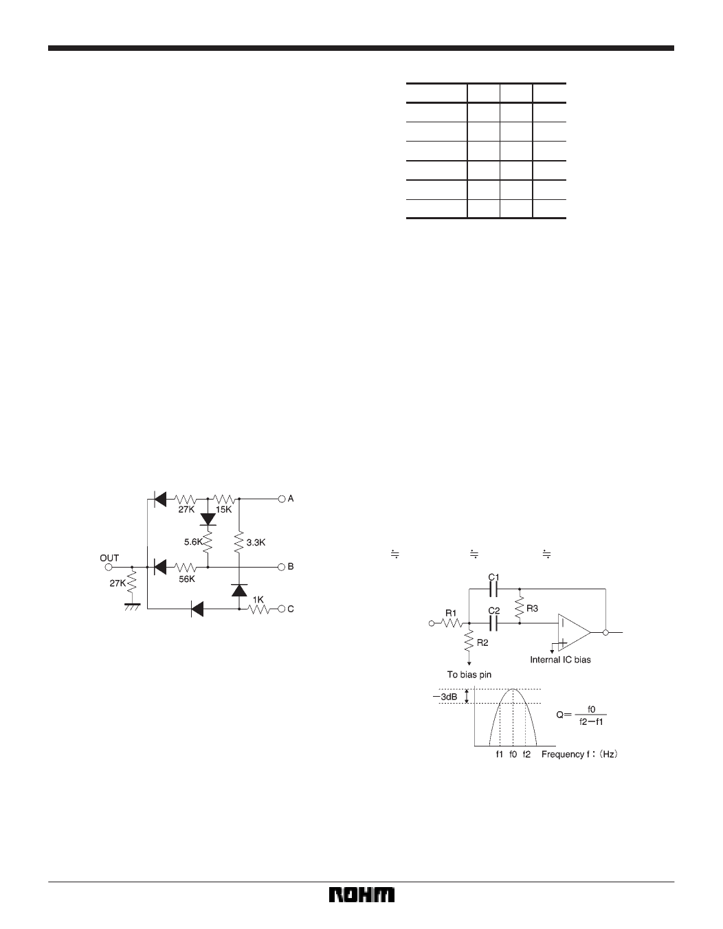
4) Here is an example of determining the control pin
voltage setting with the input of three values.
BA3842F
OUT
0V
1.3 V
3V
5V
7V
9V
CBA
LLL
L LH
LHL
L HH
HL L
HLH
L : 0V
H : VCC
(3) Input coupling capacitors
Note that the polarity of the input coupling capacitors will
change depending on the DC voltage to which they are
connected. Set capacitors based on the frequency band
to be used, taking into consideration the fact that the in-
put impedance is 50kΩ.
(4) Load resistances
If the values of the load resistors are too small, the output
gain and total harmonic distortion may fluctuate slightly.
Take this into consideration when connecting the subse-
quent stage.
(5) The dynamic bass boost filter is a multi feedback
active filter which forms the B.P.F.
FO can be changed with the C value.
fO = 1 / [2π {(R1 / / R2) R3 C1 C2}1 / 2]
Q = 1 / 2 {(R3 / (R1 / / R2)}1 / 2
HO = R3 / {R1 (1)C1 / C2)1 / 2}
When R1 = 2.4kΩ, R2 = 4.3kΩ, R3 = 91kΩ, and C1 = C2 =
0.22µF,
fO 61Hz Q 3.8 HO 19
Connect OUT to the control pin.
Regarding the values of the various constants, it is impor-
tant to consider current dissipation and other such prob-
lems. If such a problem should occur, change the
constants and redesign the diode logic.
If R1 and R2 are too small, the bass boost characteristics
such as boost gain and crosstalk may change. Keep this
in mind when setting filter values. Furthermore, design
the application so that the bass boost level increments by
5dB from 5 to 20dB when HO = 19.
572
Share Link: 