AIC1802 Просмотр технического описания (PDF) - Analog Intergrations
Номер в каталоге
Компоненты Описание
производитель
AIC1802 Datasheet PDF : 10 Pages
| |||
AIC1802
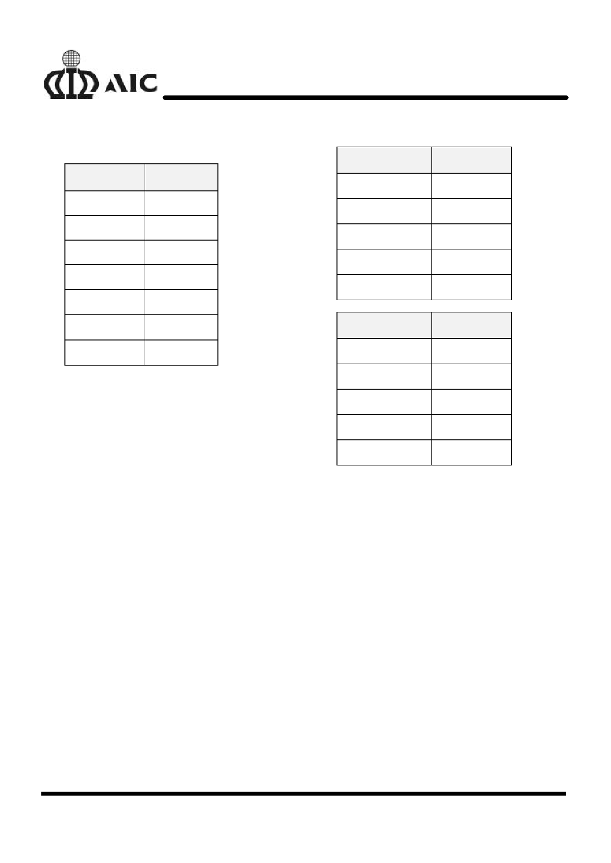
time TOI is tabulated as below.
VCS (V)
150m
200m
300m
360m
1V
3V
5V
TOI (S)
9.0m
5.6m
2.8m
2.0m
540µ
290µ
270µ
Unbalanced Discharge after Overcharge
When either of the battery cells is overcharged,
the AIC1802 will automatically discharge the
overcharged cell at about 7.7mA until the voltage
of the overcharged cell is equal to the voltage of
the other cell. If the voltage of the other cell is
below VOCR, the internal cell-balance “bleeding”
will proceed until the voltage of the overcharged
cell decreases to VOCR.
DESIGN GUIDE
Adjustment of Overcharge and
Overdischarge Delay Time
Both the overcharge and overdischarge delay
times default to 25mS and can be extended by
adding the external capacitors CTC and CTD,
respectively. Increasing the capacitance value will
increase the delay time. The relationship between
capacitance of the external capacitors and delay
time is tabulated as below:
CTC (F)
0µ
0.1µ
0.3µ
0.47 µ
0.57 µ
CTD (F)
0µ
0.1µ
0.3µ
0.47 µ
0.57 µ
TOC (S)
25m
320m
890m
1.12
1.43
TOD (S)
25m
320m
820m
1.08
1.39
Selection of External Control MOSFETs
Because the overcurrent protection voltage is
preset, the threshold current for overcurrent
detection is determined by the turn-on resistance
of the discharge control MOSFET M1. The turn-
on resistance of the external control MOSFETs
can be determined by the equation: RON=VOIP/IT
(IT is the overcurrent threshold current). For
example, if the overcurrent threshold current IT is
designed to be 5A, the turn-on resistance of the
external control MOSFETs must be 30mΩ. Users
should be aware that turn-on resistance of the
MOSFET changes with temperature variation due
to heat dissipation. It changes with the voltage
between gate and source as well. (Turn-on
resistance of a MOSFET increases as the voltage
between gate and source decreases). Once the
turn-on resistance of the external MOSFET
8
Share Link: 