SP8852EIGHCAR –Я—А–Њ—Б–Љ–Њ—В—А —В–µ—Е–љ–Є—З–µ—Б–Ї–Њ–≥–Њ –Њ–њ–Є—Б–∞–љ–Є—П (PDF) - Mitel Networks
–Э–Њ–Љ–µ—А –≤ –Ї–∞—В–∞–ї–Њ–≥–µ
–Ъ–Њ–Љ–њ–Њ–љ–µ–љ—В—Л –Ю–њ–Є—Б–∞–љ–Є–µ
–њ—А–Њ–Є–Ј–≤–Њ–і–Є—В–µ–ї—М
SP8852EIGHCAR Datasheet PDF : 13 Pages
| |||
SP8852E
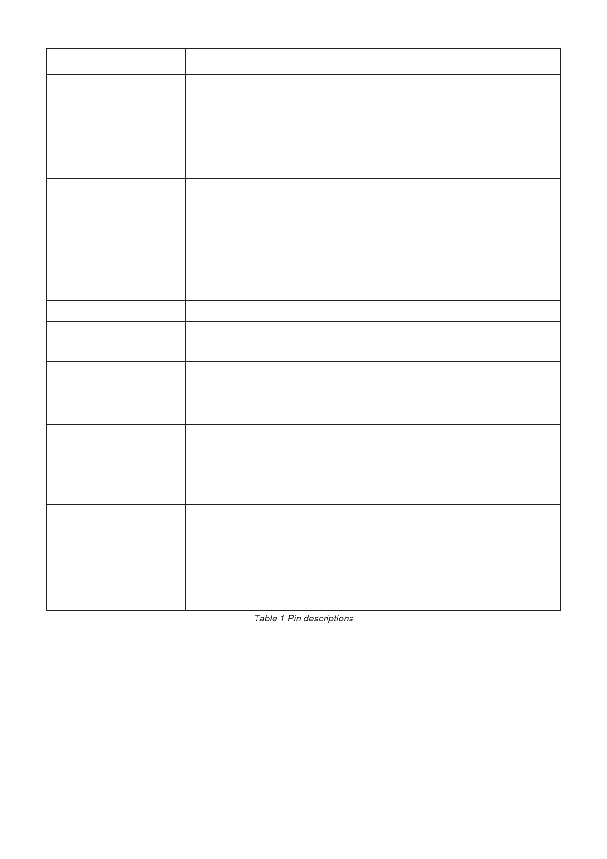
Pin
Description
1-11, 40-44
These are the inputs to the 16-bit data bus. When pin 38 is high the data goes to the buffers for
the A counter, M counter and phase detector gain. When pin 38 is low the data goes to the buffers
for the reference counter and the phase detector state (see Table 4). Open circuit = 1 (high) on
these pins. Data is transparent from pins to the selected buffers when pin 39 (STROBE) is high
and frozen in buffers when pin 39 is low.
13 (RF INPUT)
14 (RF INPUT)
Balanced inputs to the RF preamplifier. For single-ended operation the signal is AC-coupled into
pin 13 with pin 14 AC-decoupled to ground (or vice-versa). Pins 13 and 14 are internally DC
biased.
17 (LOCK DETECT INPUT)
A current sink into this pin is enabled when the lock detect circuit indicates lock. Used to give
an external indication of phase lock.
18 (C-LOCK DETECT)
A capacitor connected to this point determines the lock detect integrator time constant and can
be used to vary the sensitivity of the phase lock indicator.
19 (RSET)
20 (CHARGE PUMP OUTPUT)
21 (CHARGE PUMP REF)
An external resistor from pin 19 to VCC sets the charge pump output current.
The phase detector output is a single ended charge pump sourcing or sinking current to the
inverting input of an external loop filter. The direction is controlled by bit 12 of the reference word.
For bit 12 = 1 and FPD or RF phase leads Ref phase pin 20 will sink current (see Table 3).
Connected to the non-inverting input of the loop filter to set the optimum DC bias.
22
Not Connected.
23
Not connected.
24 FPD if pin 23 is high
FREF if pin 23 is low
25 FPD if pin 23 is low
FREF if pin 23 is high
27 (Ref. oscillator capacitor)
RF divider output pulses. FPD = RF input frequency/(M.N1A). Pulse width = 8 RF input cycles
(1 cycle of the divide by 8 prescaler output).
Reference divider output pulses. FREF = reference input frequency/R. Pulse width = high period
of Ref input.
Leave open circuit if an external reference is used. See Fig. 5 for typical connection for use as
an onboard crystal oscillator.
28 (REF IN/XTAL)
This pin is the input buffer amplifier for an external reference signal. This amplifier provides the
active element if an onboard crystal oscillator is used.
29-37
Not connected.
38 (ADDRESS)
Controls which buffer the data on the input bus goes to. Pin 38 high sends data to the RF divider
group of functions. Pin 38 low sends data to the Ref divider group of functions (see Fig. 6). Open
circuit = high.
39 (STROBE)
When pin 39 is high the A, M, and R counters are held in the reset state and the charge pump
output is disabled. The data on the input bus is loaded into the buffers selected by the ADDRESS
input state (pin 38) when pin 39 goes low. When pin 39 is low the data is fixed in the buffers, the
buffers are loaded into the counter and control register, all the counters are active, and the
charge pump is enabled. Open circuit = high.
Table 1 Pin descriptions
3
Share Link: 