PCA9556 Просмотр технического описания (PDF) - Philips Electronics
Номер в каталоге
Компоненты Описание
производитель
PCA9556 Datasheet PDF : 13 Pages
| |||
Philips Semiconductors
Octal SMBus and I2C registered interface
Product data
PCA9556
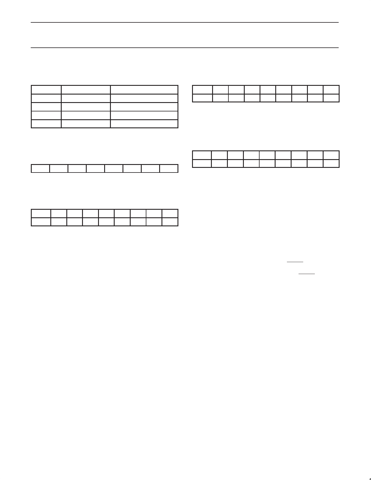
REGISTERS
Command Byte
Command
Protocol
0
Read byte
1
Read/write byte
2
Read/write byte
3
Read/write byte
Function
Input port register
Output port register
Polarity inversion register
Configuration register
The command byte is the first byte to follow the address byte during
a write transmission. It is used as a pointer to determine which of the
following registers will be written or read.
Register 0 — Input Port Register
I7
I6
I5
I4
I3
I2
I1
I0
This register is an read-only port. It reflects the incoming logic levels
of the pins, regardless of whether the pin is defined as an input or an
output by register 3. Writes to this register have no effect.
Register 1 — Output Port Register
bit O7 O6 O5 O4 O3 O2 O1 O0
default 0
0
0
0
0
0
0
0
This register reflects the outgoing logic levels of the pins defined as
outputs by register 3. Bit values in this register have no effect on
pins defined as inputs. In turn, reads from this register reflect the
value that is in the flip-flop controlling the output selection, NOT the
actual pin value.
Register 2 — Polarity Inversion Register
bit N7 N6 N5 N4 N3 N2 N1 N0
default 1
1
1
1
0
0
0
0
This register enables polarity inversion of pins defined as inputs by
register 3. If a bit in this register is set (written with ‘1’), the
corresponding port pin’s polarity is inverted. If a bit in this register is
cleared (written with a ‘0’), the corresponding port pin’s original
polarity is retained.
Register 3 — Configuration Register
bit C7 C6 C5 C4 C3 C2 C1 C0
default 1
1
1
1
1
1
1
1
This register configures the directions of the I/O pins. If a bit in this
register is set, the corresponding port pin is enabled as an input with
high impedance output driver. If a bit in this register is cleared, the
corresponding port pin is enabled as an output.
RESET
Power-on Reset
When power is applied to VDD, an internal power-on reset holds the
PCA9556 in a reset state until VDD has reached VPOR. At that point,
the reset condition is released and the PCA9556 registers and
SMBus state machine will initialize to their default states.
External Reset
A reset can be accomplished by holding the RESET pin low for a
minimum of TW. The PCA9556 registers and SMBus/I2C state
machine will be held in their default state until the RESET input is
once again high. This input typically requires a pull-up to 3.3 V VCC.
2002 Mar 28
4
Share Link: 