RMDA00400 Просмотр технического описания (PDF) - Raytheon Company
Номер в каталоге
Компоненты Описание
производитель
RMDA00400 Datasheet PDF : 5 Pages
| |||
RMDA00400
OC-768 Modulator Driver MMIC
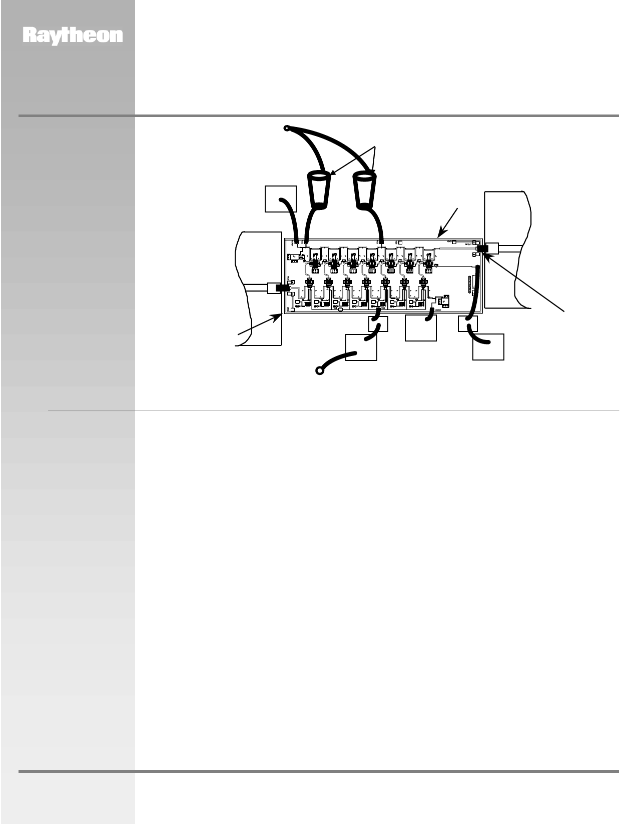
Recommended
Assembly Diagram
Vd
(+8V)
10,000pF
5mil Thick
Alumina
50-Ohm
RF
Input
Piconics
Spiral
Inductors
ADVANCED INFORMATION
Die-Attach
80Au/20Sn
5 mil Thick
Alumina
50-Ohm
RF
Output
2 mil Gap
100pF
10,000pF
Vg1
(-ve)
10,000pF
100pF
10,000pF
L< 0.015”
(2 Places)
Recommended
Procedure
for Biasing and
Operation
CAUTION: THIS IS AN ESD SENSITIVE DEVICE. LOSS OF GATE VOLTAGE (VG1) WHILE DRAIN VOLTAGE (VD) IS
PRESENT MAY DAMAGE THE AMPLIFIER CHIP.
The following sequence of steps must be followed to properly test the amplifier:
Step 1: Turn off RF input power.
Step 2: Connect the DC supply grounds to the ground
of the chip carrier.
Apply negative gate bias supply voltage of
–1.0 V to Vg1.
Step 3: Apply positive drain bias supply voltage of
+8.0 V to Vd, and monitor drain current Id.
Step 4: Adjust gate bias voltage Vg1 to set the
quiescent current of Idq ~ 130 mA.
Step 5: After the bias condition is established, the RF
input signal may now be applied at the appropriate
frequency band. Adjust Vg1 for best gain flatness.
Note: When the device is under RF operation, the
supply current Id will increase depending
upon output power required.
Step 6: Follow turn-off sequence of:
(i) Turn off RF input power.
(ii) Turn down and off drain voltage (Vd).
(iv) Turn down and off gate bias voltage (Vg1).
www.raytheon.com/micro
Characteristic performance data and specifications are subject to change without notice.
Revised November 21, 2001
Page 4
Raytheon RF Components
362 Lowell Street
Andover, MA 01810
Share Link: 