A54SX08A Просмотр технического описания (PDF) - Actel Corporation
Номер в каталоге
Компоненты Описание
производитель
A54SX08A Datasheet PDF : 108 Pages
| |||
SX-A Family FPGAs
Boundary-Scan Testing (BST)
All SX-A devices are IEEE 1149.1 compliant and offer
superior diagnostic and testing capabilities by providing
Boundary Scan Testing (BST) and probing capabilities.
The BST function is controlled through the special JTAG
pins (TMS, TDI, TCK, TDO, and TRST). The functionality of
the JTAG pins is defined by two available modes:
Dedicated and Flexible. TMS cannot be employed as a
user I/O in either mode.
Dedicated Mode
In Dedicated mode, all JTAG pins are reserved for BST;
designers cannot use them as regular I/Os. An internal
pull-up resistor is automatically enabled on both TMS
and TDI pins, and the TMS pin will function as defined in
the IEEE 1149.1 (JTAG) specification.
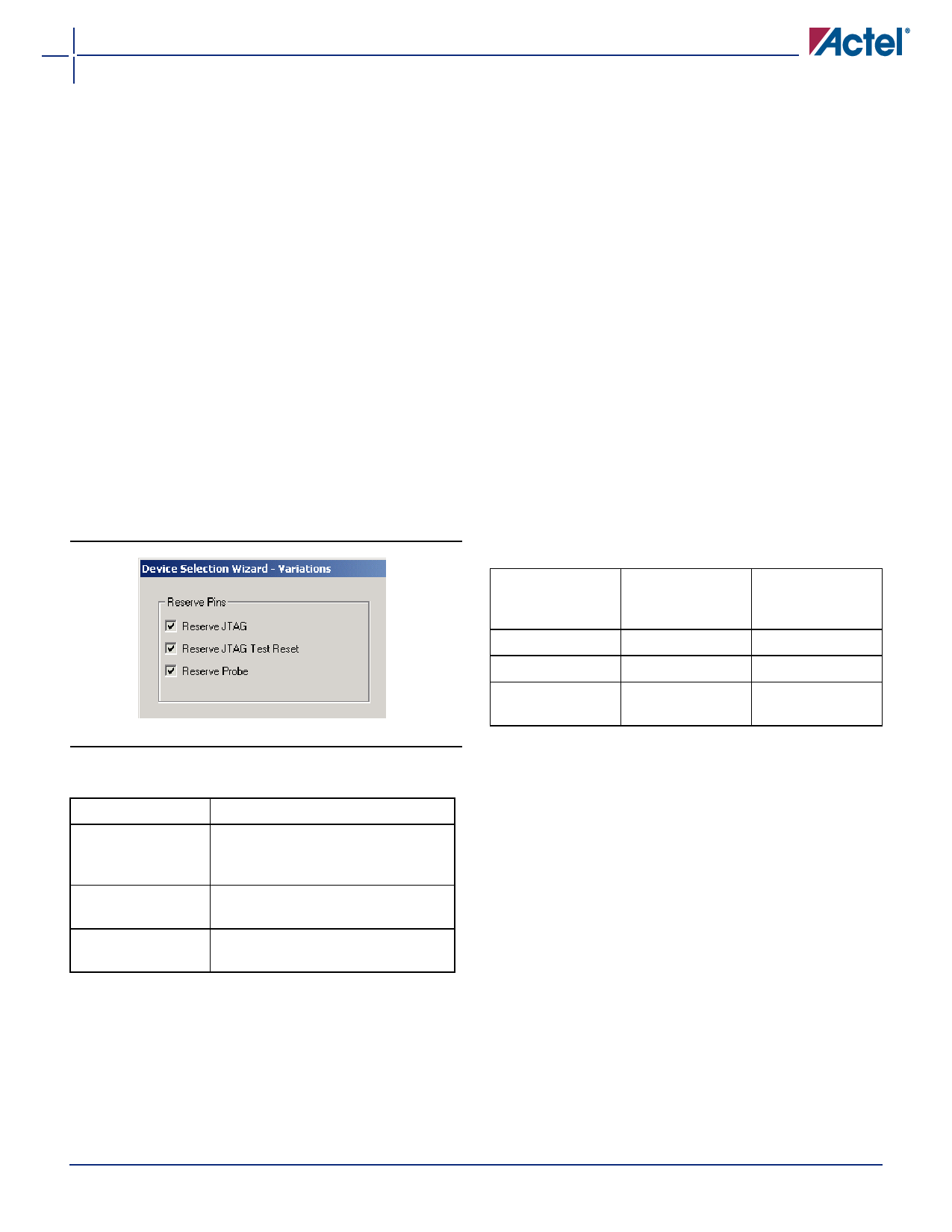
To select Dedicated mode, the user must reserve the
JTAG pins in Actel’s Designer software. Reserve the JTAG
pins by checking the Reserve JTAG box in the Device
Selection Wizard (Figure 1-12).
The default for the software is Flexible mode; all boxes
are unchecked. Table 1-5 lists the definitions of the
options in the Device Selection Wizard.
Figure 1-12 • Device Selection Wizard
Table 1-5 • Reserve Pin Definitions
Pin
Function
Reserve JTAG
Keeps pins from being used and
changes the behavior of JTAG pins (no
pull-up on TMS)
Reserve JTAG Test Regular I/O or JTAG reset with an
Reset
internal pull-up
Reserve Probe
Keeps pins from being used or regular
I/O
Flexible Mode
In Flexible mode, TDI, TCK, and TDO may be employed as
either user I/Os or as JTAG input pins. The internal
resistors on the TMS and TDI pins are not present in
flexible JTAG mode.
To select the Flexible mode, uncheck the Reserve JTAG
box in the Device Selection Wizard dialog in the Actel
Designer software. In Flexible mode, TDI, TCK, and TDO
pins may function as user I/Os or BST pins. The
functionality is controlled by the BST Test Access Port
(TAP) controller. The TAP controller receives two control
inputs, TMS and TCK. Upon power-up, the TAP controller
enters the Test-Logic-Reset state. In this state, TDI, TCK,
and TDO function as user I/Os. The TDI, TCK, and TDO are
transformed from user I/Os into BST pins when a rising
edge on TCK is detected while TMS is at logic low. To
return to Test-Logic Reset state, TMS must be high for at
least five TCK cycles. An external 10 k pull-up resistor
to VCCI should be placed on the TMS pin to pull it
High by default.
Table 1-6 describes the different configuration
requirements of BST pins and their functionality in
different modes.
Table 1-6 • Boundary-Scan Pin Configurations and
Functions
Mode
Designer
"Reserve JTAG"
Selection
TAP Controller
State
Dedicated (JTAG)
Checked
Any
Flexible (User I/O)
Unchecked
Test-Logic-Reset
Flexible (JTAG)
Unchecked
Any EXCEPT Test-
Logic-Reset
TRST Pin
The TRST pin functions as a dedicated Boundary-Scan
Reset pin when the Reserve JTAG Test Reset option is
selected as shown in Figure 1-12. An internal pull-up
resistor is permanently enabled on the TRST pin in this
mode. Actel recommends connecting this pin to ground
in normal operation to keep the JTAG state controller in
the Test-Logic-Reset state. When JTAG is being used, it
can be left floating or can be driven high.
When the Reserve JTAG Test Reset option is not
selected, this pin will function as a regular I/O. If unused
as an I/O in the design, it will be configured as a tristated
output.
v5.3
1-9
Share Link: 