AS3932 Просмотр технического описания (PDF) - austriamicrosystems AG
Номер в каталоге
Компоненты Описание
производитель
AS3932 Datasheet PDF : 33 Pages
| |||
AS3932
Data Sheet - Detailed Description
8.9.3 External Clock Source
To clock the AS3932 with an external signal the crystal oscillator has to be enabled (R1<1>=1). As shown in the Figure 3 the clock must be
applied on the pin XIN while the pin XOUT must stay floating. The RC time constant has to be 100μs with a tolerance of ±10% (e.g. R=680 kΩ
and C=22pF). In the Table 24 the clock characteristics are summarized.
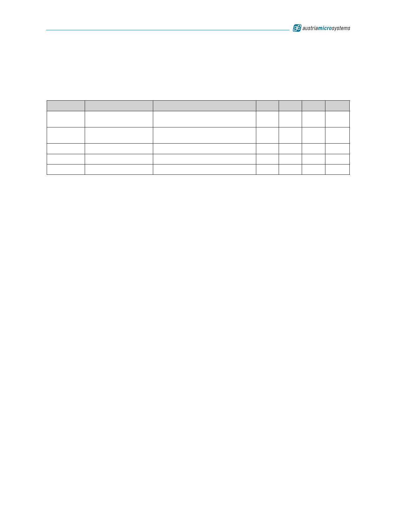
Table 24. Characteristics of External Clock
Symbol
Parameter
Conditions
Min Typ Max Units
VI
Low level
0
0.1 *
VDD
V
Vh
High level
0.9 *
VDD
VDD
V
Tr
Rise-time
3
µs
Tf
Fall-time
3
µs
T=1/2πRC
RC Time constant
90
100
110
µs
Note: In power down mode the external clock has to be set to VDD.
8.10 Channel Selection in Scanning Mode and ON/OFF Mode
In case only 2 channels are active and one of the Low Power modes is enabled, then the channels 1 and 3 have to be active. If the chip works in
On-Off mode and only one channel is active then the active channel has to be the channel 1.
Both Low Power modes are not allowed to be enabled at the same time.
www.austriamicrosystems.com/AS3932
Revision 1.2
28 - 33
Share Link: 