7432 Просмотр технического описания (PDF) - Toshiba
Номер в каталоге
Компоненты Описание
производитель
7432 Datasheet PDF : 7 Pages
| |||
TC74HCT32AP/AF/AFN
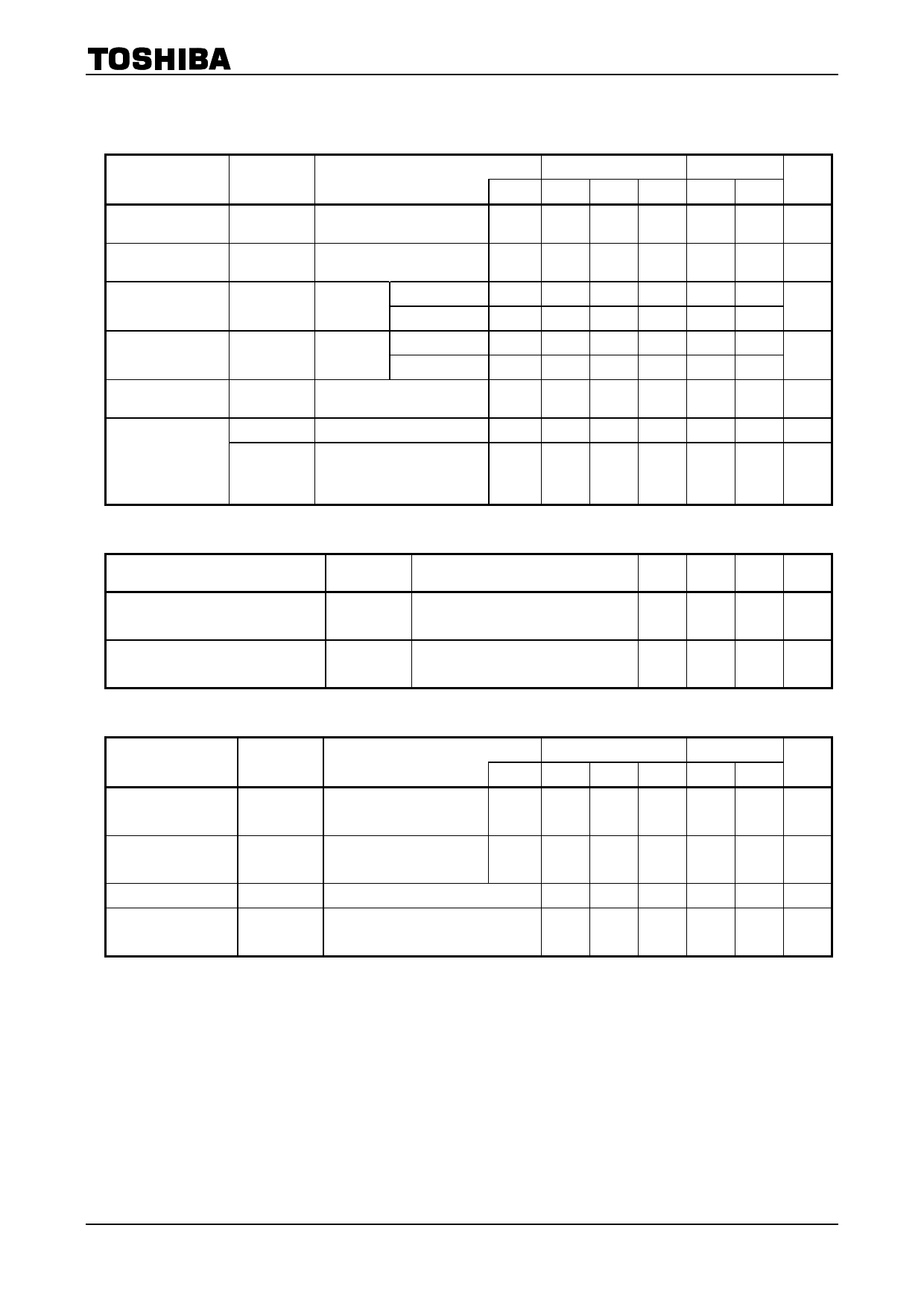
Electrical Characteristics
DC Characteristics
Characteristics
Symbol
Test Condition
High-level input
voltage
Low-level input
voltage
High-level output
voltage
Low-level output
voltage
Input leakage
current
Quiescent supply
current
VIH
VIL
VOH
VOL
IIN
ICC
IC
⎯
⎯
VIN
IOH = −20 μA
= VIH or VIL IOH = −4 mA
VIN
IOL = 20 μA
= VIH or VIL IOL = 4 mA
VIN = VCC or GND
VIN = VCC or GND
Per input:
VIN = 0.5 V or 2.4 V
Other input: VCC or GND
Ta = 25°C
Ta = −40~85°C
Unit
VCC (V) Min Typ. Max Min Max
4.5~5.5 2.0
⎯
⎯
2.0
⎯
V
4.5~5.5 ⎯
⎯
0.8
⎯
0.8
V
4.5
4.4 4.5
⎯
4.4
⎯
V
4.5 4.18 4.31 ⎯ 4.13 ⎯
4.5
⎯
0.0 0.1
⎯
0.1
V
4.5
⎯ 0.17 0.26 ⎯ 0.33
5.5
⎯
⎯ ±0.1 ⎯ ±1.0 μA
5.5
⎯
⎯
1.0
⎯ 10.0 μA
5.5
⎯
⎯
2.0
⎯
2.9 mA
AC Characteristics (CL = 15 pF, VCC = 5 V, Ta = 25°C, input: tr = tf = 6 ns)
Characteristics
Symbol
Test Condition
Min Typ. Max Unit
Output transition time
Propagation delay time
tTLH
tTHL
tpLH
tpHL
⎯
⎯
6
12
ns
⎯
⎯
10
16
ns
AC Characteristics (CL = 50 pF, input: tr = tf = 6 ns)
Characteristics
Output transition time
Propagation delay
time
Input capacitance
Power dissipation
capacitance
Symbol
tTLH
tTHL
tpLH
tpHL
CIN
CPD
(Note)
Test Condition
Ta = 25°C
Ta = −40~85°C
Unit
VCC (V) Min Typ. Max Min Max
4.5
⎯
8
15
⎯
19
⎯
ns
5.5
⎯
7
13
⎯
16
4.5
⎯
13
20
⎯
25
⎯
ns
5.5
⎯
11
18
⎯
23
⎯
⎯
5
10
⎯
10
pF
⎯
⎯
23
⎯
⎯
⎯
pF
Note:
CPD is defined as the value of the internal equivalent capacitance which is calculated from the operating
current consumption without load.
Average operating current can be obtained by the equation:
ICC (opr) = CPD・VCC・fIN + ICC/4 (per gate)
3
2007-10-01
Share Link: 