MAX8564A –ü—Ä–æ—Å–º–æ—Ç—Ä —Ç–µ—Ö–Ω–∏—á–µ—Å–∫–æ–≥–æ –æ–ø–∏—Å–∞–Ω–∏—è (PDF) - Maxim Integrated
–ù–æ–º–µ—Ä –≤ –∫–∞—Ç–∞–ª–æ–≥–µ
–ö–æ–º–ø–æ–Ω–µ–Ω—Ç—ã –û–ø–∏—Å–∞–Ω–∏–µ
–ø—Ä–æ–∏–∑–≤–æ–¥–∏—Ç–µ–ª—å
MAX8564A Datasheet PDF : 15 Pages
| |||
±1%, Ultra-Low Output Voltage, Dual and Triple
Linear n-FET Controllers
MAX8563
MAX8564
MAX8564A
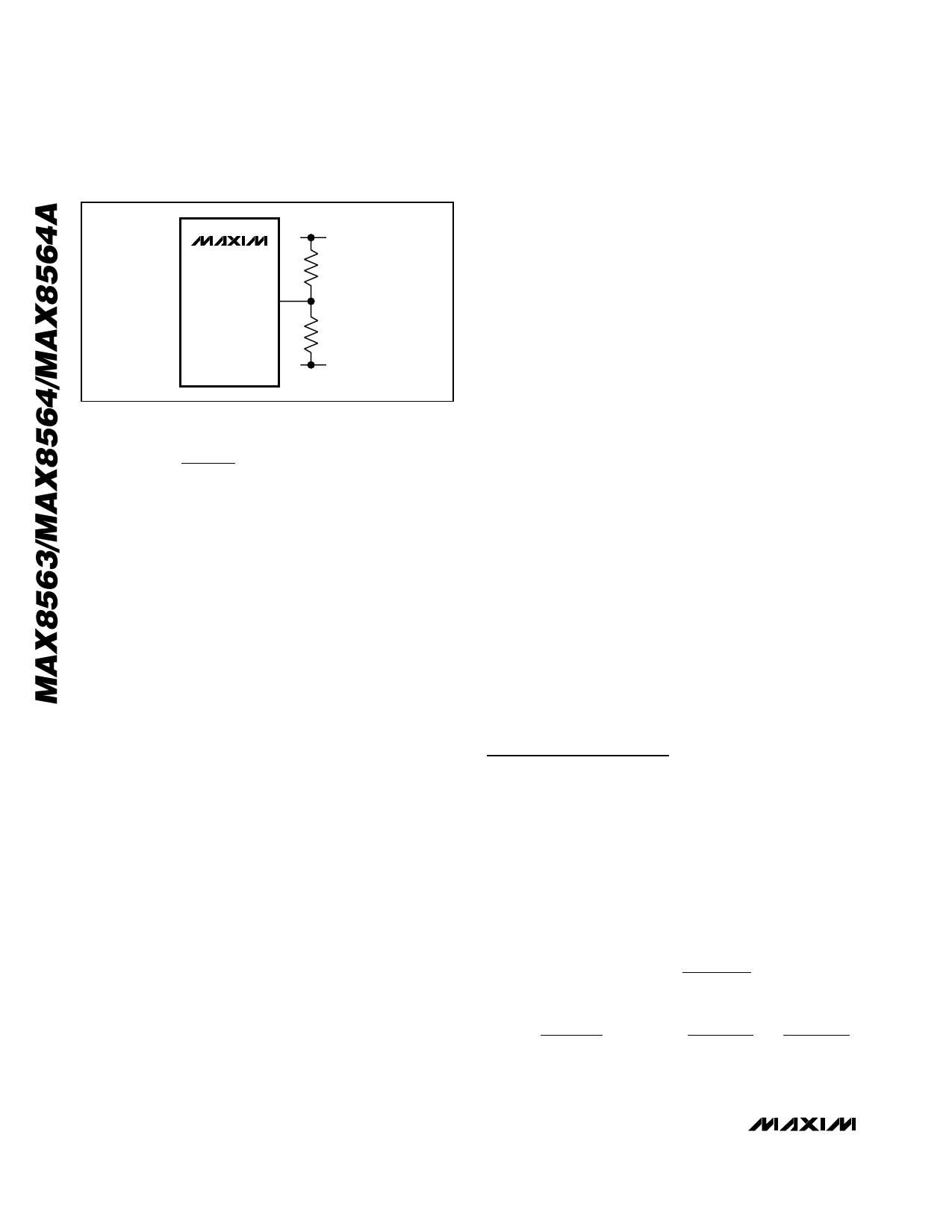
EN_
VDD
RD
RE
IN_
Figure 4. Voltage-Divider on EN_
( ) 1.3
<
‚éõ
‚éù‚éú
RE
RE + RD
‚éû
‚éÝ‚éü
√ó
VDD ‚àí VIN_
+ VIN_
Set RD = 100kΩ. The above equations also assume that
VDD > VIN_ > 1V when VIN_ is on or at a high-voltage
state, and that VDD > 3V.
Example: Connect 100kΩ from EN to VDD and 4kΩ from
EN_ to IN_. Thus, when VDD = 12V and VIN_ = 0V, then
VEN_ = 0.46V. When VDD = 12V and VIN_ = 1.2V, then
VEN_ = 1.6V.
Alternately, to avoid fault shutdown due to the delay of
VIN relative to VDD, pull EN_ low with a separate control
logic and only drive high when VIN reaches a steady-
state value.
Output Voltage
The output voltage range at the source of the n-MOSFET
is from 0.5V to 3.3V when VDD is 12V and from 0.5V to
1.8V when VDD is 5V. The maximum output voltage is a
function of the minimum gate-to-source voltage (VGS) of
the MOSFET and VDD.
The external n-MOSFET contains a parasitic diode from
source to drain. If the output is ever anticipated to
exceed the input, current flows from source to drain. If
this is undesirable, external protection is needed. A
simple solution is the placement of a diode in series,
from IN_ to the drain of the n-MOSFET, so that reverse
current is not possible. Due to the forward-voltage drop
of the diode, the maximum output voltage is reduced
and additional power is consumed in the diode.
Enable and POK
The MAX8563/MAX8564/MAX8564A have independent
enable control inputs (EN1, EN2, and EN3). Drive EN1
high to enable output 1. Drive EN2 high to enable out-
put 2. Drive EN3 high to enable output 3. When EN_ is
driven low, the corresponding DRV_ is internally pulled
to GND and POK_ is internally pulled low.
The POK_ is an open-drain output that provides the sta-
tus of the output voltage and pulls low depending upon
circuit conditions. During startup, once the FB_ reaches
the POK_ threshold, the POK_ signal goes high. The
POK_ threshold has 30mV of hysteresis. When the out-
put voltage drops 12% below the nominal regulated
voltage, POK_ pulls low. All POK_ outputs pull low
when UVLO is activated or when the internal VL regula-
tor and reference are not ready.
Output Undervoltage and
Overload Protection
When an overload event or short circuit occurs, the
device that is most vulnerable is the external n-MOSFET.
The MAX8563/MAX8564/MAX8564A monitor the output
voltage to protect the MOSFET. When DRV_ is at its maxi-
mum voltage and the output voltage drops below 80%
but is still greater than 60% of its nominal voltage for
more than 50µs, the MAX8563/MAX8564/MAX8564A
shut down that particular regulator output by pulling
DRV_ to GND. Note that there is an additional inherent
delay in turning off the MOSFET. The delay is a function
of the compensation capacitor and the MOSFET. If the
output recovers to greater than 80% within 50µs, it is not
considered to be in overload and no action is taken.
When the output voltage drops below 60% of its nominal
voltage, the MAX8563/MAX8564/MAX8564A immediately
shut down that particular regulator output by pulling
DRV_ to GND. To restart that particular LDO, VDD must
be recycled below the UVLO or the corresponding EN_
must be recycled. The overload protection is shown in
the Typical Operating Characteristics.
Design Procedure
Output Voltage Setting
The minimum output voltage for each controller of the
MAX8563/MAX8564/MAX8564A is typically 0.5V. The
maximum output voltage is adjustable up to 3.3V with
VDD = 12V, and up to 1.8V with VDD = 5V. To set the out-
put voltage, connect the FB_ pin to the center of a volt-
age-divider between OUT_ and GND (Figure 5). The
resistor-divider current should be at least 1mA per 1A of
maximum output current; i.e., for a 3A maximum output
current, set the resistor-divider bias current to ‚â• 3mA:
IOUT(MIN)
‚â•
IOUT(MAX)
1000
RB
≤
VFB
IOUT(MIN)
= 1000 √ó
VFB
IOUT(MAX)
=
500
IOUT(MAX)
10 ______________________________________________________________________________________
Share Link: 