LA1193M(1997) Просмотр технического описания (PDF) - SANYO -> Panasonic
Номер в каталоге
Компоненты Описание
производитель
LA1193M Datasheet PDF : 21 Pages
| |||
LA1193M, 1193V
6. AGC Circuit
The LA1193M/V uses pin diode antenna damping (pin 9) and MOSFET second gate voltage control (pin 16) for
AGC. The AGC operating sequence is as follows:
Antenna damping (pin diode) → MOSFET second gate voltage control
(attenuation) 20 dB
(attenuation) dB
The above AGC sequence is used for the following reasons.
• Intermodulation distortion can occur if a signal of 110 dBµ or larger is input to the antenna circuit varactor diode.
In such situations, if the AGC sequence was MOSFET second gate voltage control followed by pin diode antenna
damping, as long as the receiver was not in a strong field where the 60 dB or higher AGC attenuation operates,
input limitation due to the antenna circuit varactor diode would operate. Therefore, we feel that the AGC operating
sequence employed is appropriate.
• Consider the problem of AGC loop stability. If the two AGC loops (the antenna damping AGC loop and the
MOSFET second gate control AGC loop) operate, the AGC system would become unstable and have an
excessively large influence on the transient response. Therefore the following structure cannot be used.
MOSFET second gate control → antenna damping → MOSFET second gate control
The AGC operating conditions are the same as those for the LA1175M.
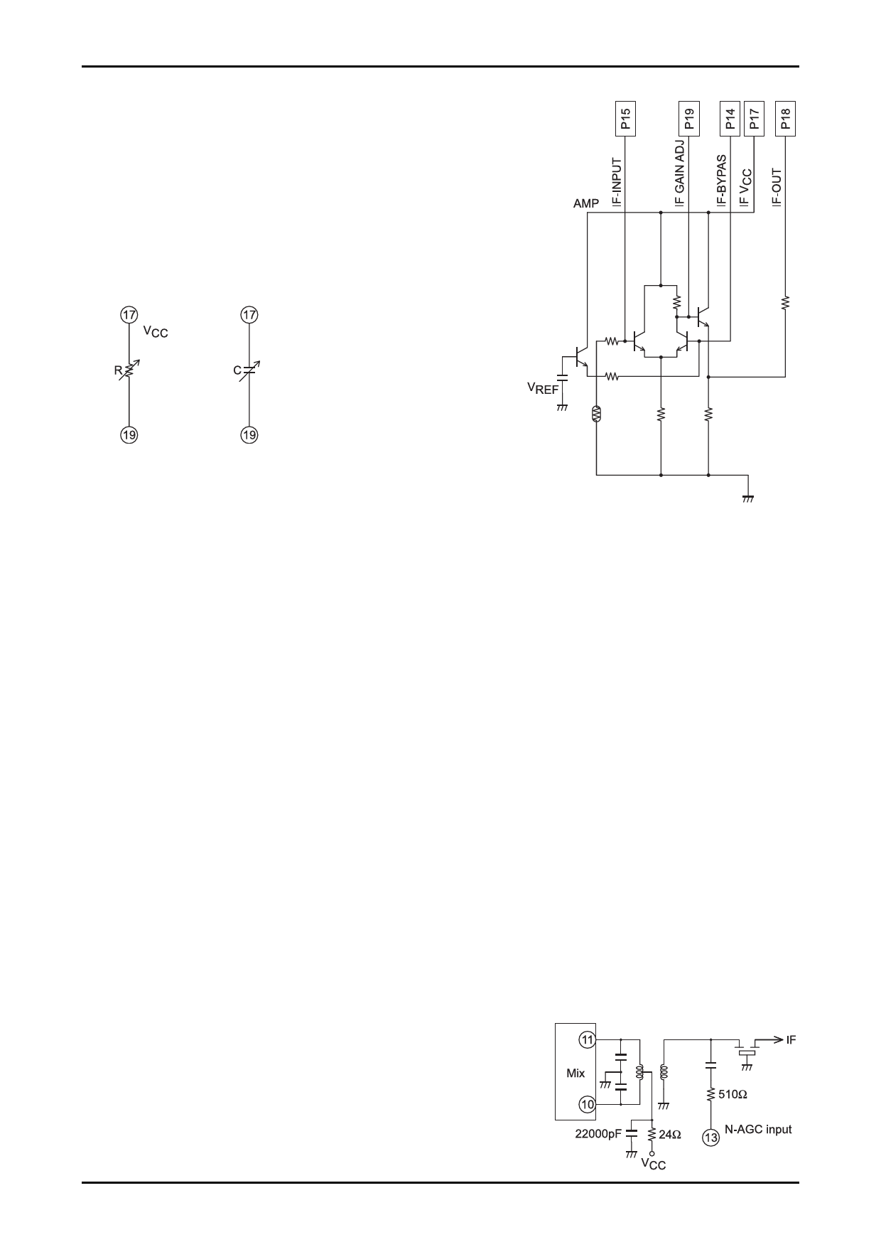
• Narrow AGC circuit
Since the LA1193M/V’s N-AGC (which detects the mixer output) is set to have a high sensitivity, care is required
to avoid incorrect operation. In particular, there must be adequate separation from the local oscillator block on the
printed circuit board pattern. Also, a resistor of at least 500 Ω must be inserted at the pin 13 input. A low-pass filter
is formed by the insertion of this resistor. This low-pass filter prevents incorrect AGC operation due to the local
oscillator.
• The AGC sensitivity setting can be changed by adjusting the
value of the capacitor connected at pin 13. Although the AGC
sensitivity can be lowered by increasing the value of the series
resistor, caution is required since the AGC has its own frequency
characteristics.
• Wide AGC circuit
The wide AGC sensitivity is set by the value of the capacitor on pin 8. However, since incorrect operation due to
the local oscillator signal may occur if this capacitor is too large, its value must be chosen carefully.
• 3D-AGC
If the difference in sensitivity between the N-AGC and the W-AGC systems is too large during 3D-AGC
operation, the S/N ratio can be degraded in the vicinity of the input where the AGC switches. Therefore, the
3D-AGC setting values must be selected carefully. Although this problem can be ameliorated by applying a time
constant to pin 20, in principle, this S/N ratio degradation should be prevented by limiting the sensitivity difference
between the two AGC systems.
No. 4715-12/21
Share Link: 