LT1228(Rev_A) Просмотр технического описания (PDF) - Linear Technology
Номер в каталоге
Компоненты Описание
производитель
LT1228 Datasheet PDF : 20 Pages
| |||
LT1228
TYPICAL APPLICATI S
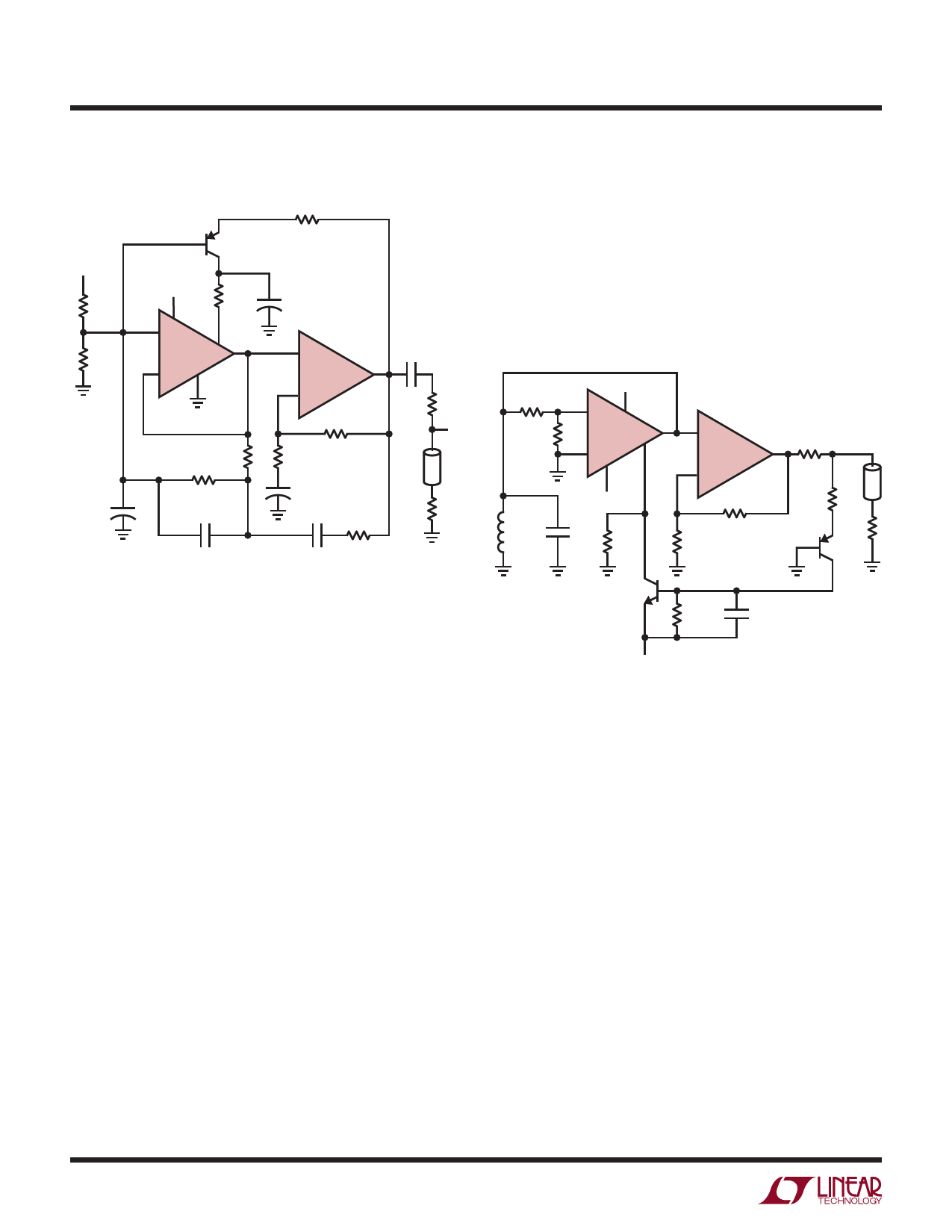
Single Supply Wien Bridge Oscillator
100Ω
V+
10kΩ
10kΩ
+
10µF
2N3906
6V TO 30V
V+
7
3+
gm
2–
4
470Ω +
10µF
5
1+
CFA
8–
RF
680Ω
0.1µF
6
51Ω
VO
1.8k
160Ω
RG
20Ω
+
10µF
1000pF
1000pF
50Ω
160Ω
f = 1MHz
VO = 6dBm (450mVRMS)
2nd HARMONIC = –38dBc
3rd HARMONIC = –54 dBc
FOR 5V OPERATION SHORT OUT 100Ω RESISTOR
LT1228 • TA14
3 at resonance; therefore the attenuation of the 1.8k resis-
tor and the transconductance amplifier must be about 11,
resulting in a set current of about 600µA at oscillation. At
start-up there is no set current and therefore no attenuation
for a net gain of about 11 around the loop. As the output
oscillation builds up it turns on the PNP transistor which
generates the set current to regulate the output voltage.
12MHz Negative Resistance LC Oscillator
9.1k
1k
V+
3+
7
gm
2–
5
4
V–
4.7µH
30pF
4.3k
1+
CFA
8–
1k
330Ω
6 51Ω
VO
750Ω
50Ω
2N3906
2N3904
10k
0.1µF
In this application the LT1228 is biased for operation from
a single supply. An artificial signal ground at half supply
voltage is generated with two 10k resistors and bypassed
with a capacitor. A capacitor is used in series with RG to set
the DC gain of the current feedback amplifier to unity.
The transconductance amplifier is used as a variable resis-
tor to control gain. A variable resistor is formed by driving
the inverting input and connecting the output back to it. The
equivalent resistor value is the inverse of the gm. This
works with the 1.8k resistor to make a variable attenuator.
The 1MHz oscillation frequency is set by the Wien bridge
network made up of two 1000pF capacitors and two 160Ω
resistors.
For clean sine wave oscillation, the circuit needs a net gain
of one around the loop. The current feedback amplifier has
a gain of 34 to keep the voltage at the transconductance
amplifier input low. The Wien bridge has an attenuation of
V–
VO = 10dB
AT VS = ±5V ALL HARMONICS 40dB DOWN
AT VS = ±12V ALL HARMONICS 50dB DOWN
LT1228 • TA15
This oscillator uses the transconductance amplifier as a
negative resistor to cause oscillation. A negative resistor
results when the positive input of the transconductance
amplifier is driven and the output is returned to it. In this
example a voltage divider is used to lower the signal level at
the positive input for less distortion. The negative resistor
will not DC bias correctly unless the output of the transcon-
ductance amplifier drives a very low resistance. Here it sees
an inductor to ground so the gain at DC is zero. The
oscillator needs negative resistance to start and that is
provided by the 4.3k resistor to pin 5. As the output level
rises it turns on the PNP transistor and in turn the NPN
which steals current from the transconductance amplifier
bias input.
16
Share Link: 