XE1205I074TRLF Просмотр технического описания (PDF) - Semtech Corporation
Номер в каталоге
Компоненты Описание
производитель
XE1205I074TRLF
Semtech Corporation

XE1205I074TRLF Datasheet PDF : 48 Pages
| |||
XE1205
data “noisy” data preacmble
pattern
/fifoempty
fifofull
Fifooverrun
(flag)
write_byte
15
0
pattern
b0 b1 b2 b3 b4 b5 b6 b7 b8 b9 b10 b11 b12 b13 b14 b15 b16
b15
b14
b13
b12
b11
b10
b9
b8
b7
b6
b5
b4
b3
b2
b1
b0
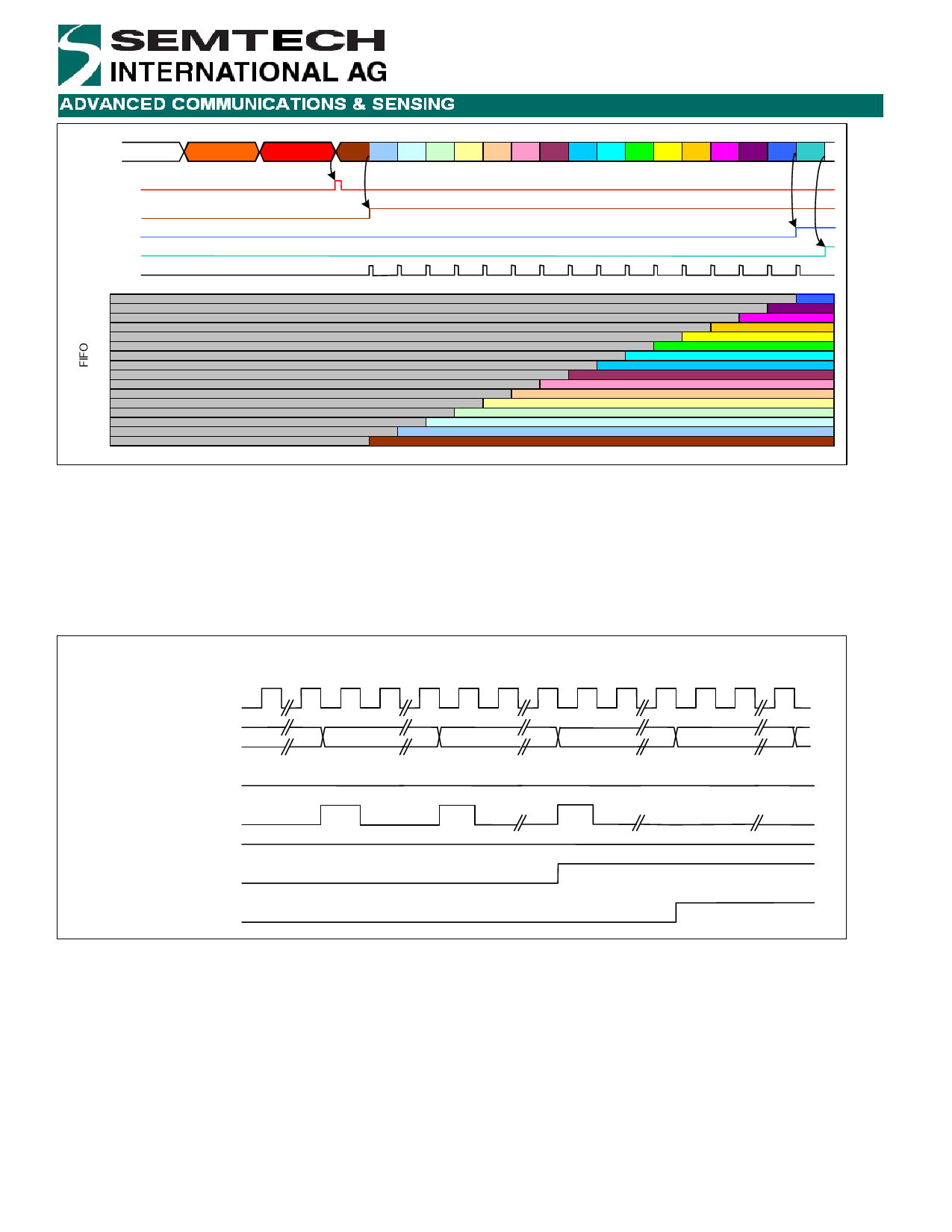
Figure 9: Start detection and FIFO filling
The FIFO filling process is shown in detail in Figure 9. As the first byte is written into the FIFO the signal /fifoempty goes
high indicating that at least one byte is present. The microcontroller can then read the contents of the FIFO via the SPI
interface. Once all data have been read from the FIFO then /fifoempty goes low. Once the last bit of the sixteenth byte
has been written into the FIFO then the signal Fifofull is asserted; data should be read before the next byte is received.
This is illustrated in Figure 10.
Completion of FIFO filling
DCLK
DATA
PATTERN
Byte 14
Byte 15
Byte 16
Byte 17
Write_byte
/Fifoempty
Fifofull
IRQParam_Fifooverrun
Figure 10: Completion of FIFO filling
The /fifoempty signal can be used as an interrupt signal for a microcontroller by mapping to pin IRQ_0 if
IRQParam_RX_irq_0 is set to “10” (please refer to section 5.2.2). Alternatively, the WRITE_BYTE signal may also be
used as an interrupt if IRQParam_RX_irq_0 is set to “01”.
5.2.5.1 Demodulator in buffered mode
Demodulation in buffered mode occurs in the same way as in continuous mode (section 5.2.3.1). Received data is
directly read from the FIFO and the DATA pin is not used.
© Semtech 2008
www.semtech.com
16
Share Link: