VDP313XY Просмотр технического описания (PDF) - Micronas
Номер в каталоге
Компоненты Описание
производитель
VDP313XY Datasheet PDF : 76 Pages
| |||
VDP 313xY
ADVANCE INFORMATION
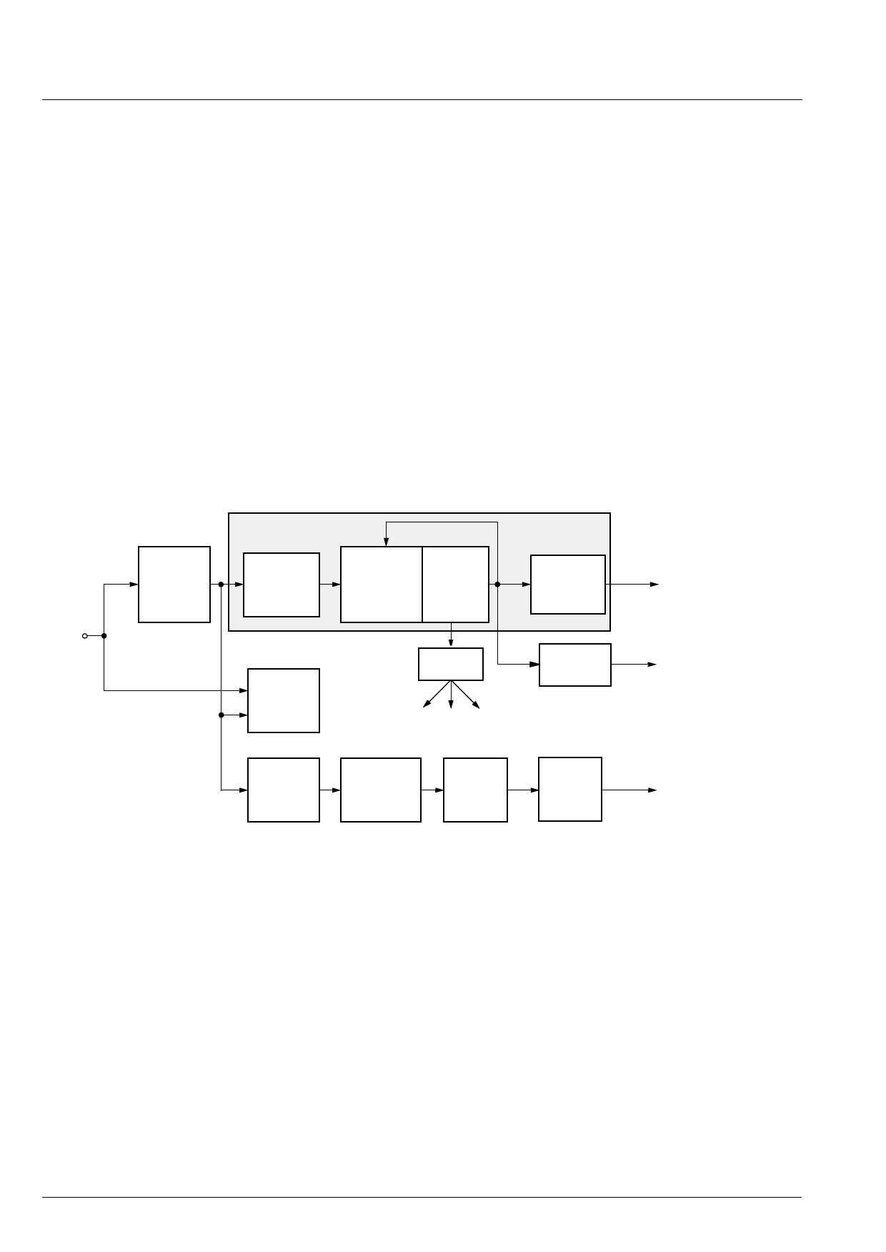
2.8. Video Sync Processing
Fig. 2–9 shows a block diagram of the front-end sync
processing. To extract the sync information from the
video signal, a linear phase lowpass filter eliminates all
noise and video contents above 1 MHz. The sync is
separated by a slicer; the sync phase is measured. A
variable window can be selected to improve the noise
immunity of the slicer. The phase comparator mea-
sures the falling edge of sync, as well as the integrated
sync pulse.
The sync phase error is filtered by a phase-locked loop
that is computed by the FP. All timing in the front-end is
derived from a counter that is part of this PLL, and it
thus counts synchronously to the video signal.
A separate hardware block measures the signal back
porch and also allows gathering the maximum/mini-
mum of the video signal. This information is processed
by the FP and used for gain control and clamping.
For vertical sync separation, the sliced video signal is
integrated. The FP uses the integrator value to derive
vertical sync and field information.
The information extracted by the video sync process-
ing is multiplexed onto the hardware front sync signal
(FSY) and is distributed to the rest of the video pro-
cessing system.
The data for the vertical deflection, the sawtooth, and
the East-West correction signal is calculated by the
VDP 313xY. The data is buffered in a FIFO and trans-
ferred to the back-end by a single wire interface.
Frequency and phase characteristics of the analog
video signal are derived from PLL1. The results are fed
to the scaler unit for data interpolation and orthogonal-
ization and to the clock synthesizer for line-locked
clock generation. Horizontal and vertical syncs are
latched with the line-locked clock.
video
input
lowpass
1 MHz
&
syncslicer
horizontal
sync
separation
phase
comparator
&
counter
lowpass
PLL1
front
sync
generator
clamp &
signal
meas.
frontend
timing
clock
synthesizer
syncs
clamping, colorkey, FIFO_write
vertical
sync
separation
Sawtooth
Parabola
Calculation
FIFO
vertical
serial
data
Fig. 2–9: Sync separation block diagram
front sync
skew
vblank
field
clock
H/V syncs
vertical
E/W
sawtooth
2.9. Macrovision detection
Video signals from Macrovision encoded VCR tapes
are decoded without loss of picture quality. However, it
might be necessary in some applications to detect the
presence of Macrovision encoded video signals. This
is possible by reading the Macrovision status register
(MCV_STATUS).
Macrovision encoded video signals typically have AGC
pulses and pseudo sync pulses added during VBI. The
amplitude of the AGC pulses is modulated in time. The
Macrovision detection logic measures the VBI lines
and compares the signal against thresholds.
The window in which the video lines are checked for
Macrovision pulses can be defined in terms of start
and stop line (e.g. 6-15 for NTSC).
14
Micronas
Share Link: 