ADM9240 Просмотр технического описания (PDF) - Analog Devices
Номер в каталоге
Компоненты Описание
производитель
ADM9240 Datasheet PDF : 22 Pages
| |||
INTERRUPT CLEARING
Reading an Interrupt Status Register will output the contents of
the Register, then clear it. It will remain cleared until the moni-
toring cycle updates it, so the next read operation should not be
performed on the register until this has happened, or the result
will be invalid. The time taken for a complete monitoring cycle
is mainly dependent on the time taken to measure the fan speeds,
as described earlier.
The INT output is cleared with the INT_Clear bit, which is Bit
3 of the Configuration Register, without affecting the contents
of the Interrupt (INT) Status Registers. When this bit is high,
the ADM9240 monitoring loop will stop. It will resume when
the bit is low.
TEMPERATURE INTERRUPT MODES
As mentioned earlier, two limit values can be programmed for
the temperature measurement, a Hot Temperature Limit (THOT),
and a Hot Temperature Hysteresis Limit (THOTHYST), which is
normally some degrees lower.
The interrupt function of the temperature sensor differs from
the interrupt operation of the other inputs in that there are three
interrupt modes, called “One-Time Interrupt” mode, “Default
Interrupt” mode and “Comparator” mode.
DEFAULT INTERRUPT MODE
Exceeding THOT causes an Interrupt that will remain active
indefinitely until reset by reading Interrupt Status Register 1 or
cleared by the INT_Clear bit in the Configuration register.
Once an Interrupt event has occurred by crossing THOT, then
reset, an Interrupt will occur again once the next temperature
conversion has completed. The interrupts will continue to occur
in this manner until the temperature goes below THOTHYST.
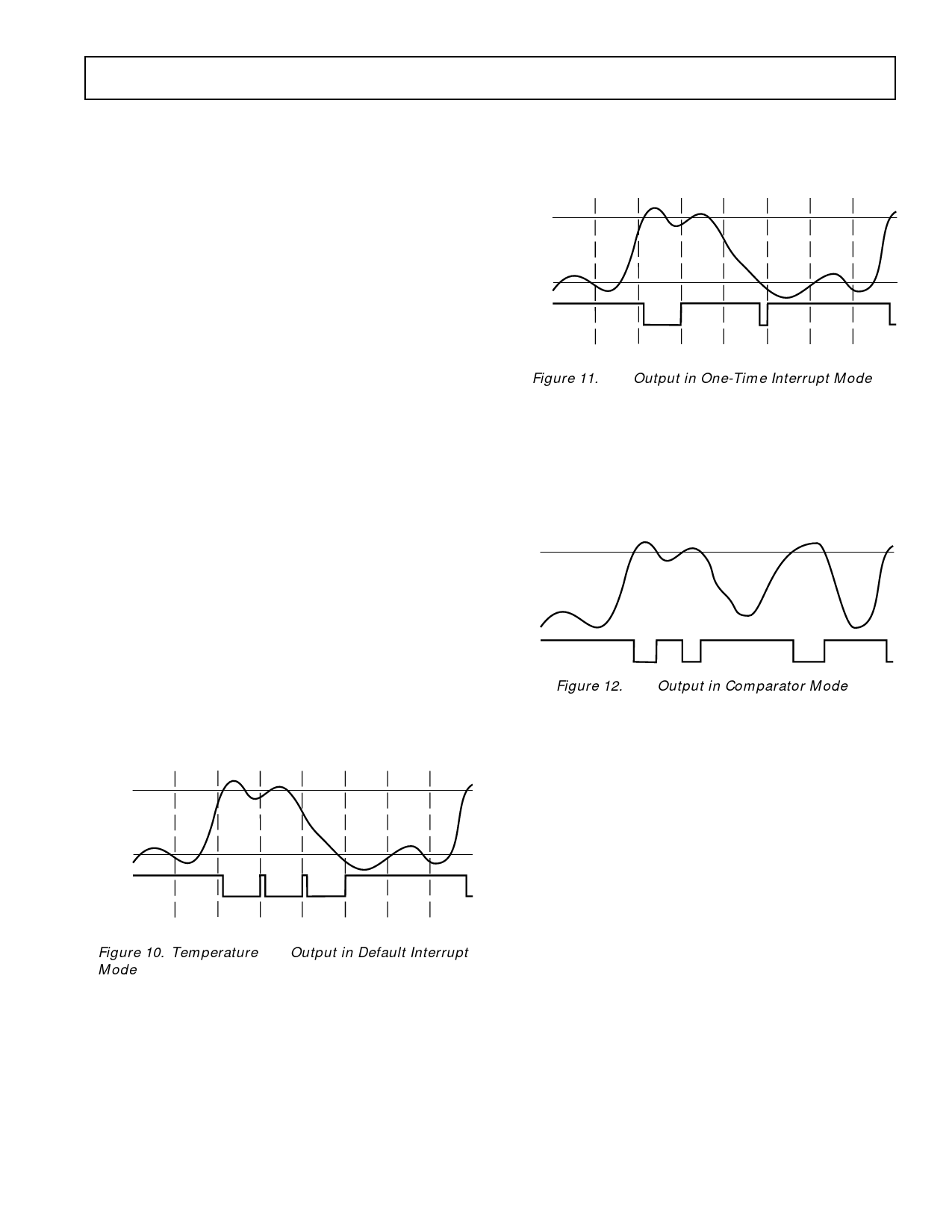
Operation in the default interrupt mode is illustrated in Figure
10. For clarity, in this illustration the interval between read
operations is shown as considerably longer than the monitoring
cycle time, so that the interrupt is always reasserted after being
reset, before the next read operation occurs.
THOT
TEMP
THOTHYST
INT
READ READ READ READ READ READ READ
Figure 10. Temperature INT Output in Default Interrupt
Mode
ONE-TIME INTERRUPT MODE
Exceeding THOT causes an Interrupt that will remain active
indefinitely until reset by reading Interrupt Status Register 1 or
cleared by the INT_Clear bit in the Configuration Register.
Once an Interrupt event has occurred by crossing THOT, then
reset, an Interrupt will not occur again until the temperature
ADM9240
goes below THOTHYST. Operation in the one-time interrupt
mode is illustrated in Figure 11. Again, the interval between
read operations is shown as being longer than the monitoring
cycle time.
THOT
TEMP
THOTHYST
INT
READ READ READ READ READ READ READ
Figure 11. INT Output in One-Time Interrupt Mode
COMPARATOR MODE
Exceeding THOT causes the INT output to go Low. INT will
remain Low until the temperature goes below THOT. Once the
temperature goes below THOT, INT will go High. THOTHYST is
ignored. In other words, Comparator Mode operates like a
thermostat with no hysteresis. Operation in the comparator
mode is illustrated in Figure 12.
THOT
TEMP
INT
Figure 12. INT Output in Comparator Mode
RESET INPUT/OUTPUT
RESET (Pin 12) is an I/O pin that can function as an open-
drain output, providing a low going 20 ms output pulse when
Bit 4 of the Configuration Register is set to 1, provided the reset
function has first been enabled by setting Bit 7 of Interrupt
Mask Register #2 to 1. The bit is automatically cleared when
the reset pulse is output. Pin 11 can also function as a RESET
input by pulling this pin low to reset the internal registers of the
ADM9240 to default values. Only those registers that have
power on default values as listed in Table VI are affected by this
function. The DAC register, Value and Limit Registers are not
affected.
NAND TREE TESTS
A NAND tree is provided in the ADM9240 for Automated Test
Equipment (ATE) board level connectivity testing. The device
is placed into NAND Test Mode by powering up with Pin 11
held high. This pin is sampled automatically after power-up and
if it connected high, then the NAND test mode is invoked.
In NAND test mode, all digital inputs may be tested as illus-
trated below. A0/NTEST_OUT will become the NAND tree
output pin. To perform a NAND tree test, all pins included in
the NAND tree should be driven high.
REV. 0
–15–
Share Link: 