TDA9809 Просмотр технического описания (PDF) - Philips Electronics
Номер в каталоге
Компоненты Описание
производитель
TDA9809 Datasheet PDF : 40 Pages
| |||
Philips Semiconductors
Single standard multimedia IF-PLL and FM
radio demodulator
Preliminary specification
TDA9809M
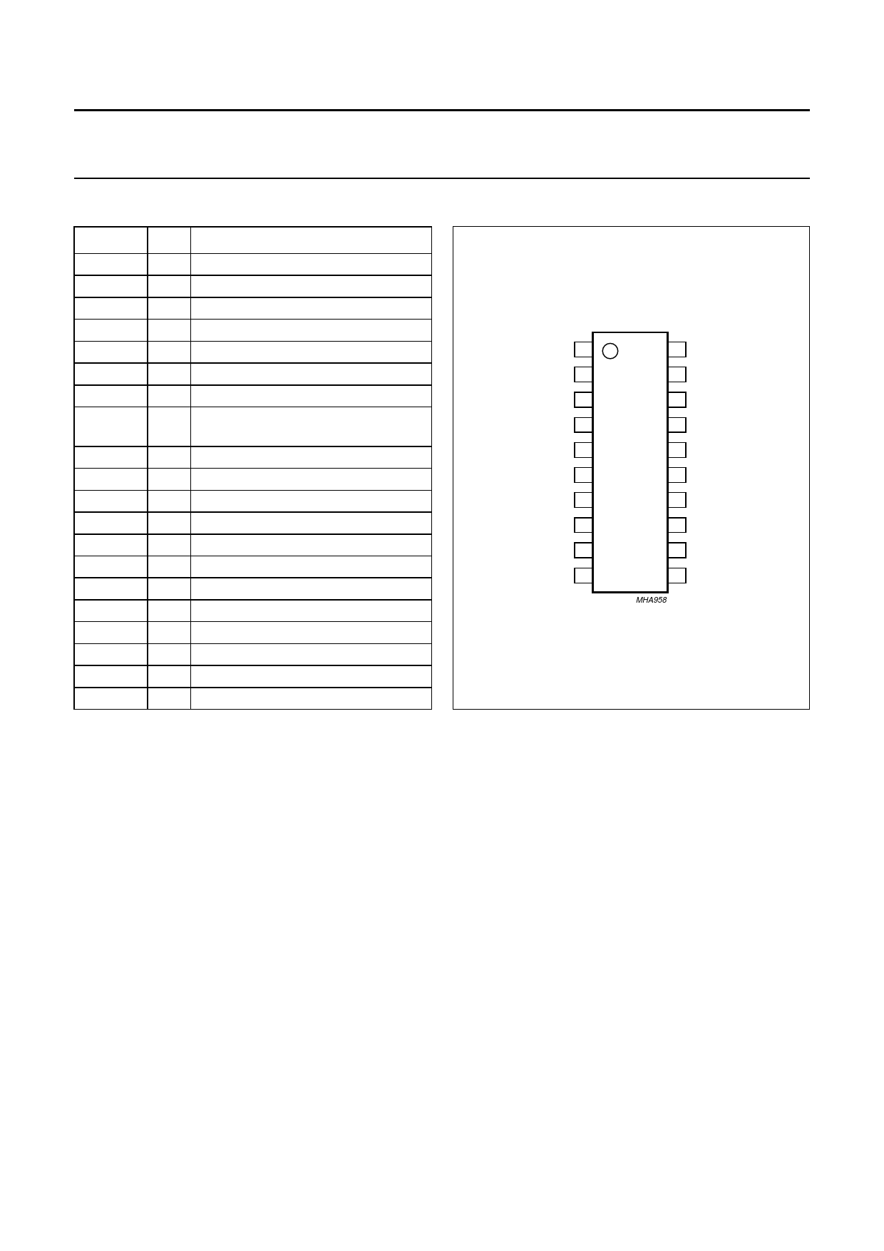
PINNING
SYMBOL PIN
DESCRIPTION
ViVIF1
ViVIF2
LP0
1 VIF differential input signal voltage 1
2 VIF differential input signal voltage 2
3 logic port 0
ViRIF
CVAGC
TPLL
VoAF
LP2
4 RIF input
5 VIF AGC capacitor
6 PLL loop filter
7 audio output
8
logic port 2 and soft mute threshold
adjustment
CDEC
Vo(int)
ViFM
TAGC
9 decoupling capacitor
10 intercarrier output voltage
11 sound intercarrier input voltage
12 TV/radio tuner AGC output
Vo(vid)
AFC
13 composite video output voltage
14 AFC/RIF level output
VCO1
15 VCO1 resonance circuit
VCO2
16 VCO2 resonance circuit
GND
17 ground
CERRES 18 ceramic resonator 10.7 MHz
VP
TADJ
19 supply voltage
20 tuner AGC takeover point adjustment
handbook, halfpage
ViVIF1 1
ViVIF2 2
LP0 3
20 TADJ
19 VP
18 CERRES
ViRIF 4
17 GND
CVAGC 5
16 VCO2
TDA9809M
TPLL 6
15 VCO1
VoAF 7
14 AFC
LP2 8
13 Vo(vid)
CDEC 9
12 TAGC
Vo(int) 10
11 ViFM
MHA958
Fig.2 Pin configuration.
FUNCTIONAL DESCRIPTION
The TDA9809M is comprised of the functional blocks
shown in Fig.1:
• Vision IF amplifier and AGC detector
• Tuner (TV/radio) and VIF AGC
• Frequency Phase-Locked Loop (FPLL) detector
• VCO, Travelling Wave Divider (TWD) and TV AFC
• Video demodulator and amplifier
• Intercarrier mixer
• RIF amplifier and AGC detector
• FM-PLL demodulator, level detector and radio AFC
• Audio Frequency (AF) signal processing
• Internal voltage stabilizer
• Logic.
Vision IF amplifier and AGC detector
The vision IF amplifier contains three AC-coupled
differential amplifier stages. Each differential stage
includes a feedback network controlled by emitter
degeneration.
The AGC detector generates the required VIF gain control
voltage for constant video output by charging/discharging
the AGC capacitor. The sync level of the video signal is
therefore detected for negative video modulation.
Tuner (TV/radio) and VIF AGC
For TV operation, the AGC capacitor voltage is converted
to an internal IF control signal and then fed to the tuner
AGC to generate the tuner AGC output current at
pin TAGC (open-collector output). The tuner AGC
takeover point can be adjusted at pin TADJ. This allows
the tuner to be matched to the SAW filter in order to
achieve the optimum IF input level.
For FM radio operation, an AGC detector is provided to
obtain some adjacent channel protection.
1998 Jan 08
5
Share Link: 