P80C562 Просмотр технического описания (PDF) - Philips Electronics
Номер в каталоге
Компоненты Описание
производитель
P80C562 Datasheet PDF : 52 Pages
| |||
Philips Semiconductors
8-bit microcontroller
Product specification
P83C562; P80C562
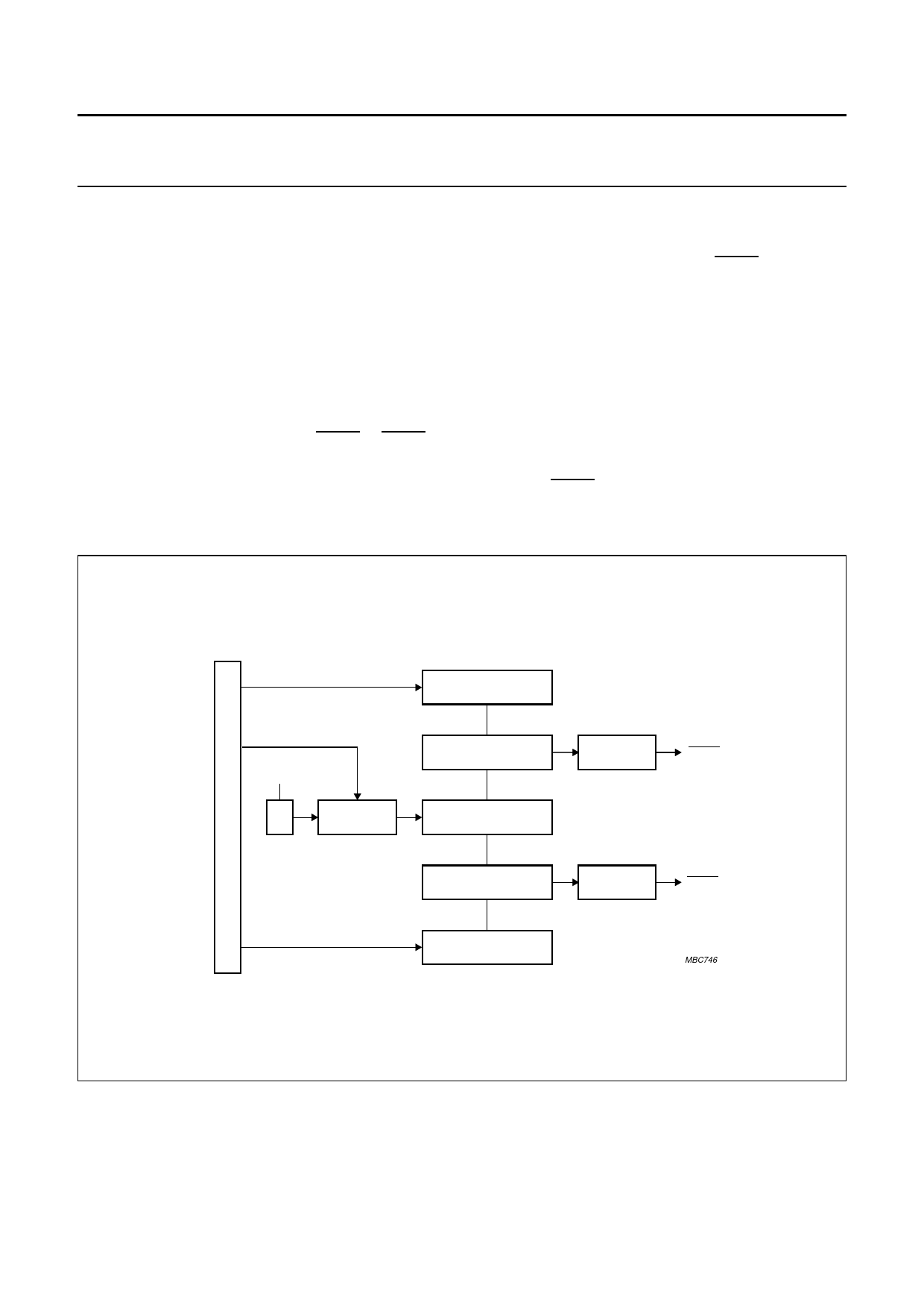
10 PULSE WIDTH MODULATED OUTPUTS
Two pulse width modulated output channels are provided
with the P8xC562. These channels output pulses of
programmable length and interval. The repetition
frequency is defined by an 8-bit prescaler PWMP which
generates the clock for the counter. Both the prescaler and
counter are common to both PWM channels. The 8-bit
counter counts modulo 255 i.e. from 0 to 254 inclusive.
The value of the 8-bit counter is compared to the contents
of two registers: PWM0 and PWM1.
Provided the contents of either of these registers is greater
than the counter value, the output of PWM0 or PWM1 is
set LOW. If the contents of these registers are equal to, or
less than the counter value, the output will be HIGH.
The pulse width ratio is therefore defined by the contents
of the registers PWM0 and PWM1.
The pulse width ratio is in the range of 0 to 255/255 and
may be programmed in increments of 1/255.
The repetition frequency fPWM, at the PWMn outputs is
given by: fPWM = 2-----×------(---1-----+-----P-f--O-W---S--M-C----P-----)----×-----2---5----5-
When using an oscillator frequency of 16 MHz for
example, the above formula would give a repetition
frequency range of 123 Hz to 31.4 kHz.
By loading the PWM registers with either 00H or FFH, the
PWM outputs can be retained at a constant HIGH or LOW
level respectively. When loading FFH to the PWM
registers, the 8-bit counter will never actually reach this
value. Both PWMn output pins are driven by push-pull
drivers, and are not shared with any other function.
handbook, full pagewidth
PMW0
I
N
T
E
f osc
R
N
A
L
1/2
PRESCALER
B
U
PWMP
S
8-BIT COMPARATOR
8-BIT COUNTER
8-BIT
COMPARATOR
OUTPUT
BUFFER
PWM0
OUTPUT
BUFFER
PWM1
PWM1
MBC746
Fig.8 Functional diagram of Pulse Width Modulated outputs.
1997 Apr 08
14
Share Link: 