P2041A-08SR Просмотр технического описания (PDF) - Alliance Semiconductor
Номер в каталоге
Компоненты Описание
производитель
P2041A-08SR Datasheet PDF : 9 Pages
| |||
November 2003
P2041A
rev F
Spread spectrum selection
Table 1 illustrates the possible spread spectrum options. The optimal setting should minimize system EMI to the
fullest without affecting system performance. The spreading is described as a percentage deviation of the center
frequency (Note: the center frequency is the frequency of the external reference input on CLKIN, Pin 1).
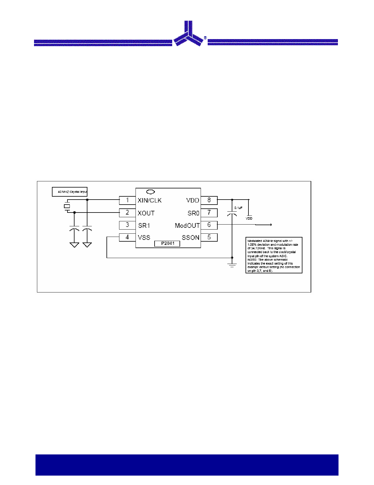
Example of a typical printer or scanner application that operates on a clock frequency of 40 MHz:
A spreading selection of SR1=1 and SR0=1 provides a percentage deviation of +/-1.00%* (see Table 1) of Fcen.
This results in the frequency on ModOUT being swept from 40.40 MHz to 39.60 MHz at a modulation rate of
40/40*34.72=34.72 KHz (see Table 1). This particular example (see Figure below) given here is a common EMI
reduction method for scanners and has already been implemented by most of the leading manufacturers.
NOTE: Spreading range selection varies from different system manufacturers and their designs. The spreading range of P2041 can be set
to +/-2.5% when working with certain scanner model.
P2041 Application Schematic for Flat-Bed Scanner
Versatile EMI Reduction IC
Notice: The information in this document is subject to change without notice.
3 of 9
Share Link: 