NCP1251 Просмотр технического описания (PDF) - ON Semiconductor
Номер в каталоге
Компоненты Описание
производитель
NCP1251 Datasheet PDF : 24 Pages
| |||
NCP1251
15 V. Under 3 mA and neglecting the series diode forward
drop, it requires a series resistor of:
ROVP
+ Vlatch * VVOP + 18 * 3 + 15 + 5 kW
VOVPńROPPL
3ń1k 3m
(eq. 16)
In nominal conditions, the plateau establishes to around
14 V. Given the divide−by−6 ratio, the OPP pin will swing
to 14/6 = 2.3 V during normal conditions, leaving 700 mV
margin. A 100 pF capacitor can be added between the OPP
pin and GND to improve noise immunity and avoid erratic
trips in presence of external surges. Do not increase this
capacitor too much otherwise the OPP signal will be affected
by the integrating time constant.
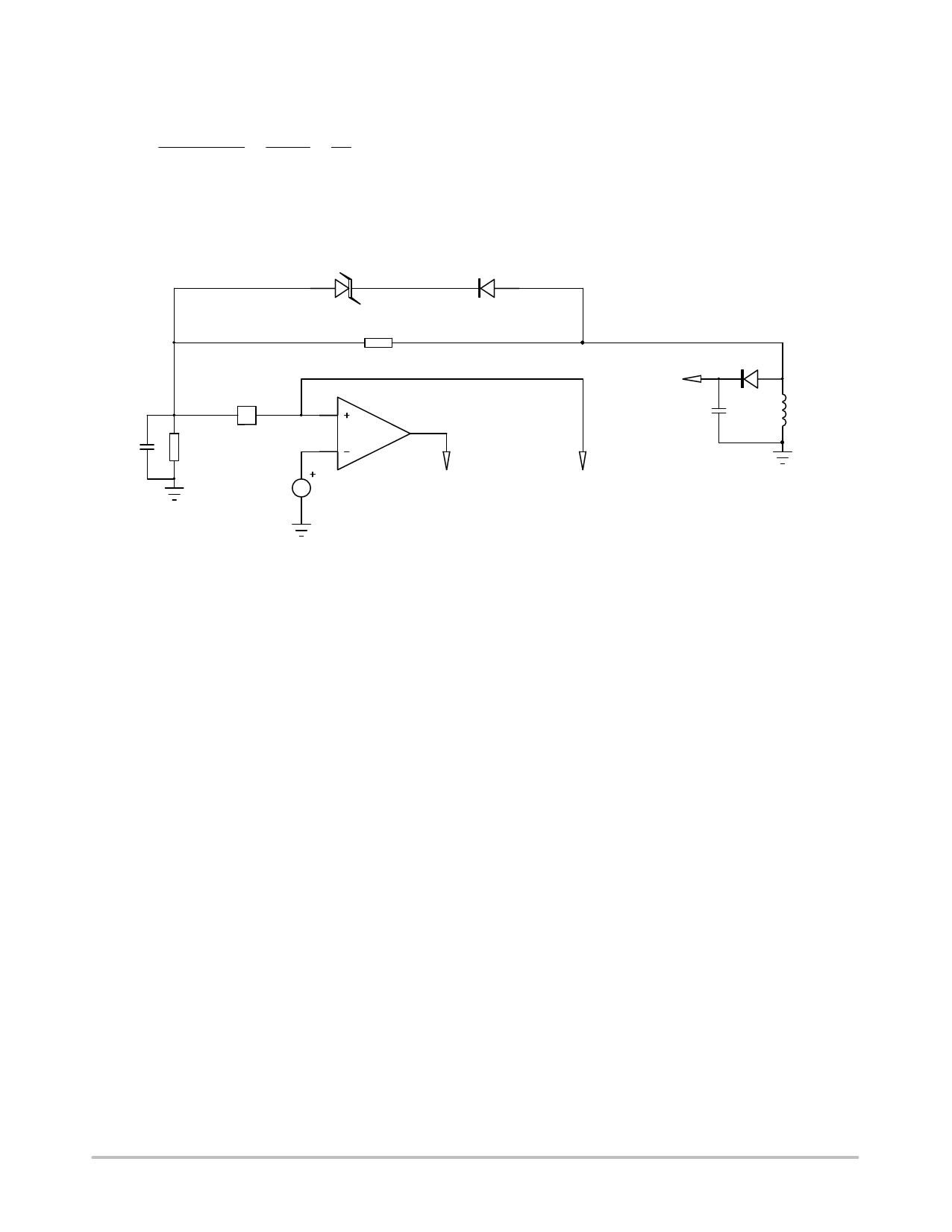
A second solution for the OVP detection alone, is to use
a Zener diode wired as recommended by.
D3
15V
11
ROPPU
421k
D2
1N4148
OPP
10
4
ROPPL
C1
1k
5
22pF
Vlatch
1
OVP
OPP
VCC
9
8
aux.
winding
Figure 48. A Zener Diode in Series with a Diode Helps to Improve the Noise Immunity of the System
For this configuration to maintain an 18 V level, we have
selected a 15 V Zener diode. In nominal conditions, the
voltage on the OPP pin is almost 0 V during the off time as
the Zener is fully blocked. This technique clearly improves
the noise immunity of the system compared to that obtained
from a resistive string as in Figure 47. Please note the
reduction of the capacitor on the OPP pin to 10 pF − 22 pF.
This capacitor is necessary because of the potential spike
coupling through the Zener parasitic capacitance from the
bias winding due to the leakage inductance. Despite the 1 ms
blanking delay at turn off. This spike is energetic enough to
charge the added capacitor C1 and given the time constant,
could make it discharge slower, potentially disturbing the
blanking circuit. When implementing the Zener option, it is
important to carefully observe the OPP pin voltage (short
probe connections!) and check that enough margin exists to
that respect.
Over Temperature Protection
In a lot of designs, the adapter must be protected against
thermal runaways, e.g. when the temperature inside the
adapter box increases above a certain value. Figure 49
shows how to implement a simple OTP using an external
NTC and a series diode. The principle remains the same:
make sure the OPP network is not affected by the additional
NTC hence the presence of this isolation diode. When the
NTC resistance decreases as the temperature increases, the
voltage on the OPP pin during the off time will slowly
increase and, once it passes 3 V for 4 consecutive clock
cycles, the controller will permanently latch off.
http://onsemi.com
21
Share Link: 