HI5728/6INZ Просмотр технического описания (PDF) - Intersil
Номер в каталоге
Компоненты Описание
производитель
HI5728/6INZ Datasheet PDF : 17 Pages
| |||
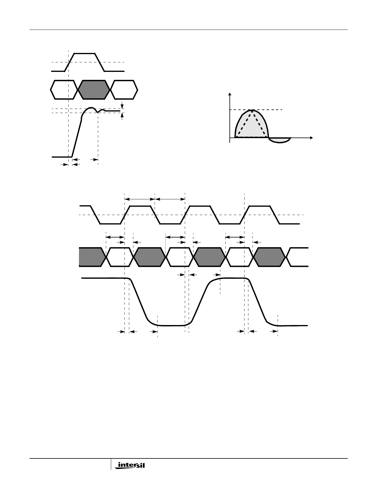
Timing Diagrams
CLK
50%
HI5728
D9-D0
IOUT
1 LSB ERROR BAND
tSETT
tPD
FIGURE 39. OUTPUT SETTLING TIME DIAGRAM
tPW1
tPW2
CLK
D9-D0
tSU
tSU
tHLD
tPD
V
GLITCH AREA = 1/2 (H x W)
HEIGHT (H)
WIDTH (W)
t (ps)
FIGURE 40. PEAK GLITCH AREA (SINGLET) MEASUREMENT
METHOD
tSU
tHLD
tHLD
tSETT
50%
IOUT
tPD
tSETT
tPD
tSETT
FIGURE 41. PROPAGATION DELAY, SETUP TIME, HOLD TIME AND MINIMUM PULSE WIDTH DIAGRAM
Definition of Specifications
Integral Linearity Error, INL, is the measure of the worst
case point that deviates from a best fit straight line of data
values along the transfer curve.
Differential Linearity Error, DNL, is the measure of the
step size output deviation from code to code. Ideally the step
size should be 1 LSB. A DNL specification of 1 LSB or less
guarantees monotonicity.
Output Settling Time, is the time required for the output
voltage to settle to within a specified error band measured
from the beginning of the output transition. The
measurement was done by switching from code 0 to 256, or
quarter scale. Termination impedance was 25Ω due to the
parallel resistance of the output 50Ω and the oscilloscope’s
50Ω input. This also aids the ability to resolve the specified
error band without overdriving the oscilloscope.
Singlet Glitch Area, is the switching transient appearing on
the output during a code transition. It is measured as the
area under the overshoot portion of the curve and is
expressed as a Volt-Time specification. This is tested under
the same conditions as “Output Settling Time, (tSETT)” on
page 6
16
FN4321.5
January 22, 2010
Share Link: 