MAX3622 Просмотр технического описания (PDF) - Maxim Integrated
Номер в каталоге
Компоненты Описание
производитель
MAX3622 Datasheet PDF : 9 Pages
| |||
Low-Jitter, Precision Clock Generator
with Two Outputs
+3.3V ±5%
VCC
10.5Ω
0.01μF
VCCA
0.01μF 10μF
Figure 2. Analog Supply Filtering
MAX3622
C9
C 10
Y1
25MHz
CRYSTAL
Applications Information
Power-Supply Filtering
The MAX3622 is a mixed analog/digital IC. The PLL
contains analog circuitry susceptible to random noise.
In addition to excellent on-chip power-supply noise
rejection, the MAX3622 provides a separate power-
supply pin, VCCA, for the VCO circuitry. Figure 2 illus-
trates the recommended power-supply filter network for
VCCA. The purpose of this design technique is to
ensure clean input power supply to the VCO circuitry
and to improve the overall immunity to power-supply
noise. This network requires that the power supply is
+3.3V ±5%. Decoupling capacitors should be used on
all other supply pins for best performance.
Crystal Selection
The crystal oscillator is designed to drive a fundamen-
tal mode, AT-cut crystal resonator. See Table 1 for rec-
ommended crystal specifications. See Figure 4 for
external capacitor connection.
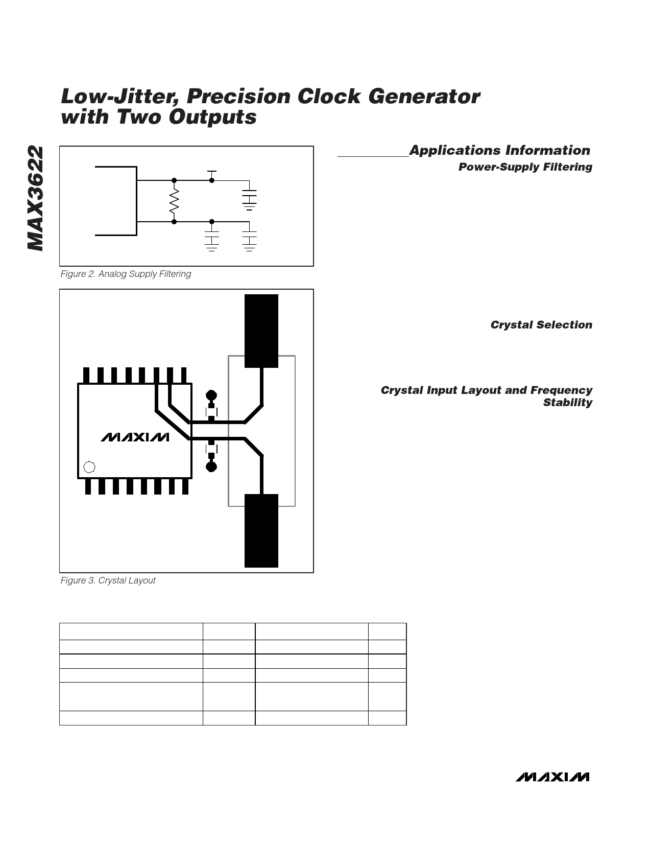
Crystal Input Layout and Frequency
Stability
The crystal, trace, and two external capacitors should
be placed on the board as close as possible to the
MAX3622’s X_IN and X_OUT pins to reduce crosstalk
of active signals into the oscillator.
The layout shown in Figure 3 gives approximately 3pF
of trace plus footprint capacitance per side of the crys-
tal (Y1). The dielectric material is FR-4 and dielectric
thickness of the reference board is 15 mils. Using a
25MHz crystal and the capacitor values of C10 = 27pF
and C9 = 33pF, the measured output frequency accu-
racy is -10ppm at +25°C ambient temperature.
Figure 3. Crystal Layout
Table 1. Crystal Selection Parameters
PARAMETER
Crystal Oscillation Frequency
Shunt Capacitance
Load Capacitance
Equivalent Series Resistance
(ESR)
Maximum Crystal Drive Level
SYMBOL MIN
fOSC
CO
CL
RS
TYP
25
2.0
18
MAX
7.0
50
300
UNITS
MHz
pF
pF
μW
6 _______________________________________________________________________________________
Share Link: 