MASWSS0162TR Просмотр технического описания (PDF) - M/A-COM Technology Solutions, Inc.
Номер в каталоге
Компоненты Описание
производитель
MASWSS0162TR Datasheet PDF : 4 Pages
| |||
MASWSS0162
GaAs SPST Switch
DC - 2.5 GHz
Electrical Specifications: TA = +25°C5, VC = -5 V / 0 V, PIN = 0 dBm
Parameter
Test Conditions
Units Min
Insertion Loss 6
Isolation 6
VSWR On
VSWR Off
1 dB Compression
Trise, Tfall
DC - 0.5 GHz
0.5 - 1.0 GHz
1.0 - 2.0 GHz
DC - 0.5 GHz
0.5 - 1.0 GHz
1.0 - 2.0 GHz
DC - 2.0 GHz
DC - 2.0 GHz
Input Power
0.05 GHz
0.5 - 2.0 GHz
10% to 90% RF, 90% to 10% RF
dB
—
dB
—
dB
—
dB
—
dB
45
dB
—
Ratio
—
Ratio
—
dBm
—
dBm
—
nS
—
Ton, Toff
50% Control to 90% RF, Control to 10% RF
nS
—
Transients
In-Band
mV
—
Measured Relative to Input Power, two-tone up to +5 dBm
2nd Order Intercept
0.05 GHz
dBm
—
0.5 - 2.0 GHz
dBm
—
Measured Relative to Input Power, two-tone up to +5 dBm
3rd Order Intercept
0.05 GHz
dBm
—
0.5 - 2.0 GHz
dBm
—
Control Current
—
µA
—
5. All measurements with 0, -5 V control voltages at 1.0 GHz in a 50 Ω system, unless otherwise specified.
6. Typical values listed are based on average of frequency range noted.
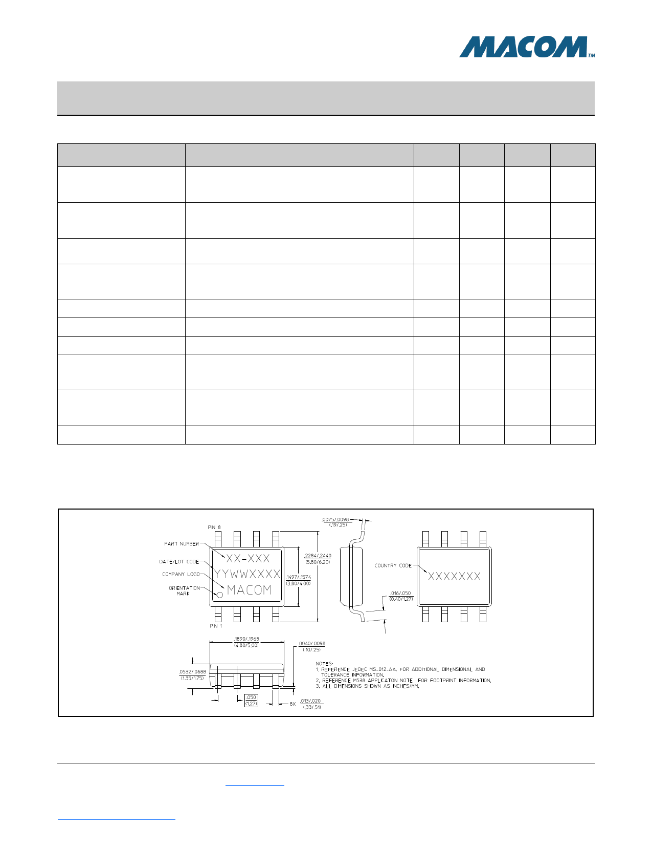
Lead-Free SOIC-8†
Rev. V3
Typ5
0.8
0.9
1.1
65
53
40
1.2:1
1.2:1
18
23
4
8
35
55
68
40
46
—
Max
—
1.2
—
—
—
—
—
—
—
—
—
—
—
—
25
† Reference Application Note M538 for lead-free solder reflow recommendations.
2
M/A-COM Technology Solutions Inc. (MACOM) and its affiliates reserve the right to make changes to the product(s) or information contained herein without notice.
Visit www.macom.com for additional data sheets and product information.
For further information and support please visit:
https://www.macom.com/support
Share Link: 