EL5120T Просмотр технического описания (PDF) - Intersil
Номер в каталоге
Компоненты Описание
производитель
EL5120T Datasheet PDF : 14 Pages
| |||
EL5120T
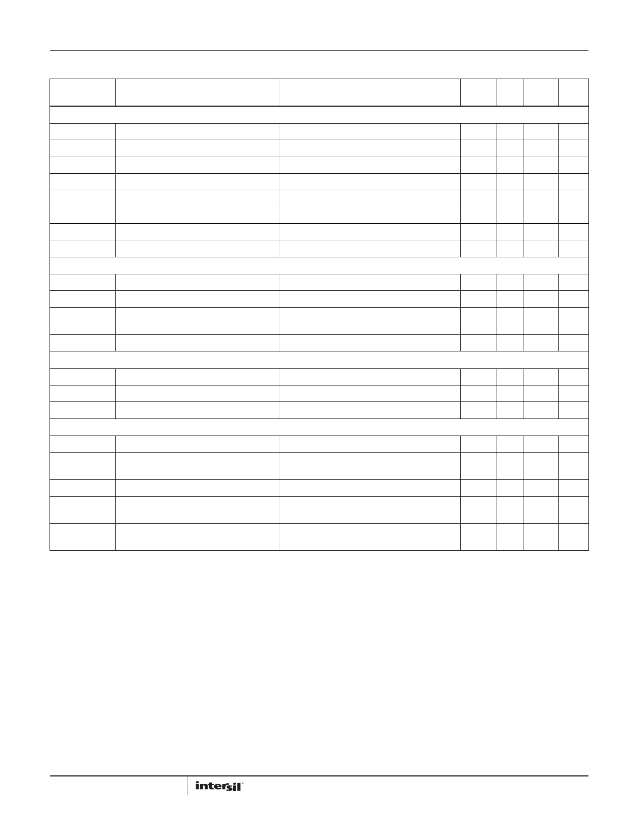
Electrical Specifications VS+ = +18V, VS- = 0V, RL = 10kΩ to 9V, TA = +25°C, unless otherwise specified.
PARAMETER
DESCRIPTION
CONDITIONS
MIN
MAX
(Note 9) TYP (Note 9) UNIT
INPUT CHARACTERISTICS
VOS
TCVOS
IB
RIN
CIN
CMIR
Input Offset Voltage
Average Offset Voltage Drift (Note 6)
Input Bias Current
Input Impedance
Input Capacitance
Common-Mode Input Range
VCM = 9V
VCM = 9V
6
18
mV
6
µV/°C
2
50
nA
1
GΩ
2
pF
-0.5
+18.5 V
CMRR
Common-Mode Rejection Ratio
AVOL
Open Loop Gain
OUTPUT CHARACTERISTICS
For VIN from -0.5V to +18.5V
0.5V ≤ VOUT ≤ 17.5V
53 78
dB
75 90
dB
VOL
Output Swing Low
VOH
Output Swing High
ISC
Short Circuit Current
IOUT
Output Current
POWER SUPPLY PERFORMANCE
IL = -9mA
IL = +9mA
VCM = 9V, Source: VOUT short to VS-,
Sink: VOUT short to VS+
120 150 mV
17.85 17.88
V
±200
mA
±70
mA
(VS+) - (VS-)
IS
PSRR
Supply Voltage Range
Supply Current
Power Supply Rejection Ratio
VCM = 9V, No load
Supply is moved from 4.5V to 19V
4.5
19
V
900 1100 µA
60 75
dB
DYNAMIC PERFORMANCE
SR
Slew Rate (Note 7)
1V ≤ VOUT ≤ 17V, 20% to 80%
12
V/µs
tS
Settling to +0.1% (Note 8)
AV = +1, VOUT = 2V step,
RL = 10kΩ, CL = 8pF
500
ns
BW
-3dB Bandwidth
RL = 10kΩ, CL = 8pF
12
MHz
GBWP
Gain-Bandwidth Product
AV = -50, RF = 5kΩ, RG = 100Ω
RL = 10kΩ, CL = 8pF
8
MHz
PM
Phase Margin
AV = -50, RF = 5kΩ, RG = 100Ω
RL = 10kΩ, CL = 8pF
50
°
NOTES:
6. Measured over -40°C to +85°C ambient operating temperature range. See the typical TCVOS production distribution shown in the “Typical
Performance Curves” on page 6.
7. Typical slew rate is an average of the slew rates measured on the rising (20% to 80%) and the falling (80% to 20%) edges of the output signal.
8. Settling time measured as the time from when the output level crosses the final value on rising/falling edge to when the output level settles within a
±0.1% error band. The range of the error band is determined by: Final Value(V)±[Full Scale(V)*0.1%]
9. Compliance to datasheet limits is assured by one or more methods: production test, characterization and/or design.
5
FN6895.0
September 27, 2012
Share Link: 