E602204_HD64413A Просмотр технического описания (PDF) - Mitsumi
Номер в каталоге
Компоненты Описание
производитель
E602204_HD64413A Datasheet PDF : 387 Pages
| |||
J.3 Video Decoder
J.3.1 Field Control by Video Decoder
66 MHz
16
Q2SD
CLK0 VHS
VVS
VODD
VQCLK
VIN7
to
VIN0
NTSC
video decoder
10 µF
HRESET
VRESET YIN
Vin
FIELD
QCLK
75 Ω
8
VD15
to
VD8
VD7
to
VD0
SDA
SCL
OE
CPU-bus
32
SDRAM
+5 V
8
I2C driver
SDRAM
SCL
SDA
28.63 MHz
+3.3 V
5V/3.3V
PCA9515
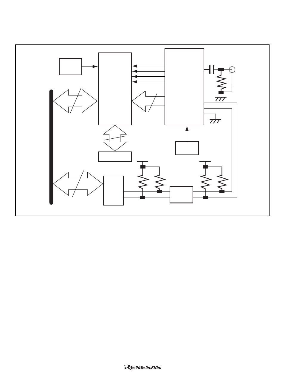
Figure J.7 Example of Connection of Video Capture Circuit
Since the video decoder in this figure is a mixed-analog-digital device with a 5-V power-supply
and a 3.3-V digital interface, the I2C interface requires conversion from 5 V to 3.3V.
The Q2SD and video decoder are only connected by the eight data lines (VIN0 to VIN7), sync-
signal lines (VHS and VVS), sync-clock line (VQCLK), and field-signal line (VODD).
The I2C driver connected to the video decoder via the PCA9515 is used to set the video decoder
by the CPU.
The combination of fields in interlacing by the Q2SD can be switched to match the source. Since
the combination of fields (top and bottom fields) is not explicitly stipulated in the NTSC
specification, two combinations are possible. Most video decoders, therefore, include a polarity-
inversion function for the FIELD signal.
Rev. 2.0, 09/02, page 363 of 366
Share Link: 