LCX023CMT Просмотр технического описания (PDF) - Sony Semiconductor
Номер в каталоге
Компоненты Описание
производитель
LCX023CMT Datasheet PDF : 26 Pages
| |||
LCX023CMT
2. LCD Panel Operations
[Description of basic operations]
• A vertical driver, which consists of vertical shift registers, enable-gates and buffers, applies a selected pulse
to every 768 gate lines sequentially in a single horizontal scanning period. (XGA mode)
• A horizontal driver, which consists of horizontal shift registers, gates and CMOS sample-and-hold circuits,
applies selected pulses to every 1024 signal electrodes sequentially in a single horizontal scanning period.
These pulses are used to supply the sampled video signal to the row signal lines.
• Vertical and horizontal shift registers address one pixel, and then Thin Film Transistors (TFTs; two TFTs) turn
on to apply a video signal to the dot. The same procedures lead to the entire 768 × 1024 dots to display a
picture in a single vertical scanning period.
• The data and video signals shall be input with the 1H-inverted system.
[Description of operating mode]
This LCD panel can change the active area by displaying a black frame to support various computer or video
signals. The active area is switched by HB, VB and BLK. However, the center of the screen is not changed.
The active area setting modes are shown below.
HB
VB
BLK
Screen aspect ratio
H
H
H
L
H
H
H
L
∗1
4:3
1024 × 768
5:4∗2
960 × 768
8:5
1024 × 640
∗1 Input BLK pulse (refer to drive waveform and vertical blanking period of PC98 made).
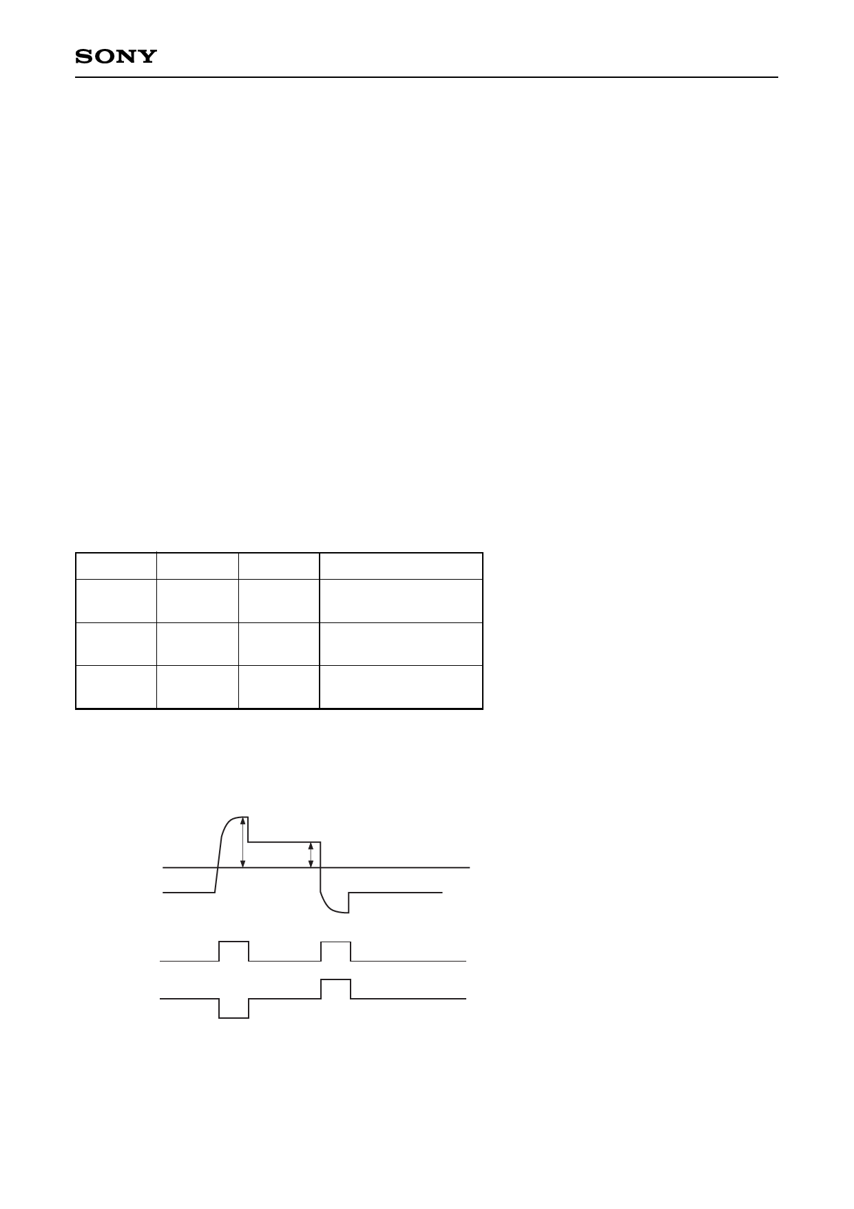
∗2 For only aspect ratio 5:4 mode, set Psig and COM voltage as shown below. The value of PsigG and COM
voltage is typical value. It is necessary to optimize the voltage for each set construction.
VVC + 4.5 [V]
VVC + 1.0 [V]
VVC
Psig
Psig B Psig G
VVC – 1.0 [V]
VVC – 4.5 [V]
PRG∗3
COM
VCOM + 2.0
VCOM
VCOM – 2.0
∗3 PRG shows the time of the 1st step of Psig signal, and it is not input to the panel.
– 18 –
Share Link: 