TC820CLW Просмотр технического описания (PDF) - TelCom Semiconductor Inc => Microchip
Номер в каталоге
Компоненты Описание
производитель
TC820CLW
TelCom Semiconductor Inc => Microchip

TC820CLW Datasheet PDF : 22 Pages
| |||
TC820
3-3/4 A/D CONVERTER WITH
FREQUENCY COUNTER
AND LOGIC PROBE
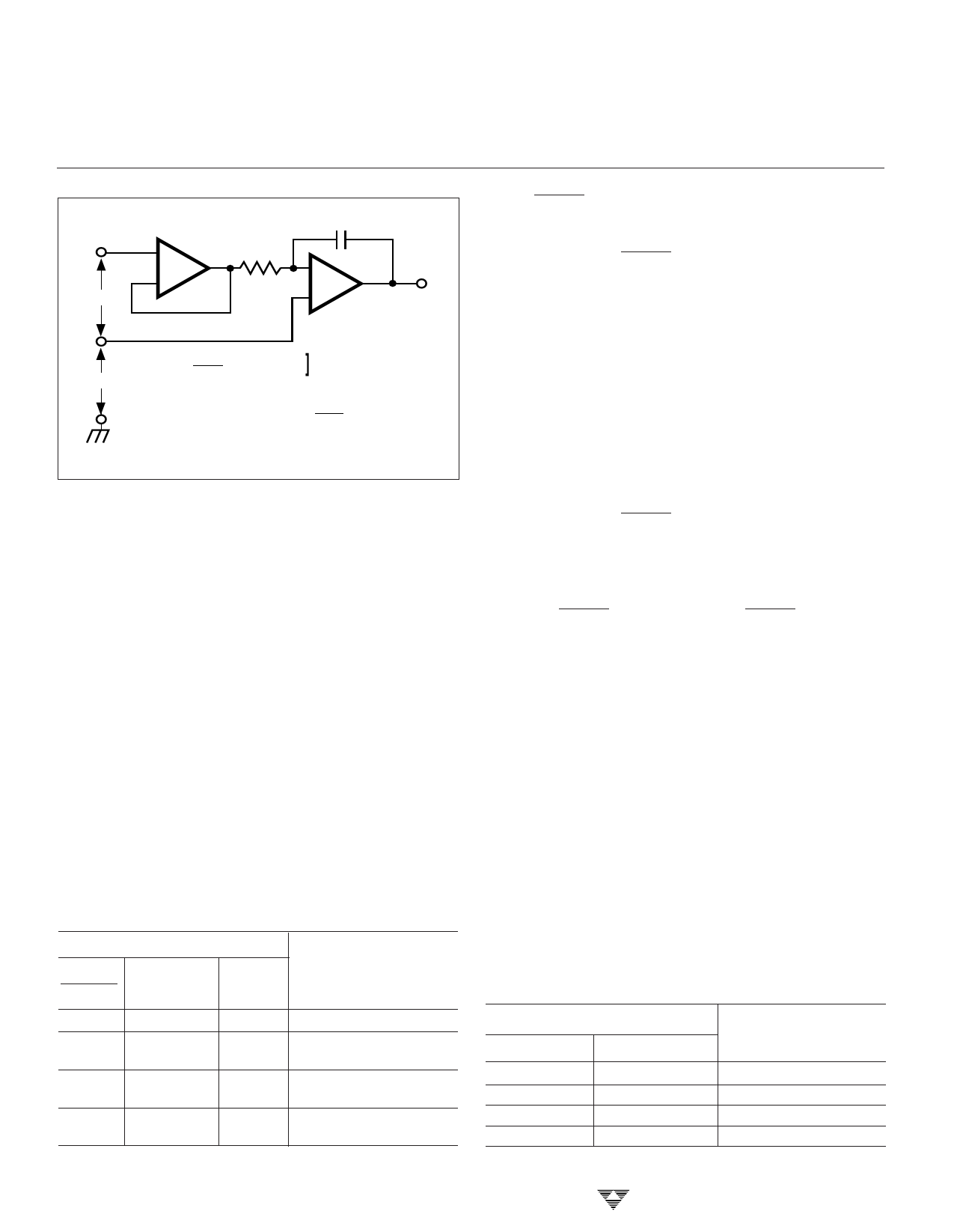
+
VIN
INPUT
BUFFER
+
RI
–
CI
–
VI
+
INTEGRATOR
–
VCM
[ VI
=
TI
RI CI
VCM – VIN
Where:
TI= Integration Time = 4000
fOSC
CI= Integration Capacitor
RI= Integration Resistor
Figure 9. Common-Mode Voltage Reduces Available
Integrator Swing (VCOM VIN)
system where input signals are not referenced (float)
with respect to the TC820 power source. The analog common
potential of VDD – 3.3V gives a 7V end-of-battery-life voltage.
The analog common potential has a voltage coefficient of
0.001%/%.
With a sufficiently high total supply voltage (VDD – VSS
> 7V), analog common is a very stable potential with excellent
temperature stability (typically 35ppm/°C). This potential
can be used to generate the TC820 reference voltage. An
external voltage reference will be unnecessary in most
cases, because of the 35ppm/°C temperature coefficient.
See the applications section for details.
Function Control Input Pin
Functional Description
The TC820 operating modes are selected with the
function control inputs. The control input truth table is shown
in Table I. The high logic threshold is ≥ VDD - 1.5V and the
low logic level is ≤ DGND +1.5V.
Table I. TC820 Control Input Truth Table
Logic Input
FREQ/
VOLTS
X
0
RANGE/
FREQ
X
0
LOGIC
1
0
0
1
0
1
Frequency
0
Counter Input
NOTES: 1. Logic "0" = DGND
2. Logic "1" = VDD
3-162
TC820
Function
Logic Probe
A/D Converter,
VFULL SCALE = 2 ϫVREF
A/D Converter,
VFULL SCALE = 20 ϫVREF
Frequency Counter
FREQ/VOLTS
This input determines whether the TC820 is in the
analog-to-digital conversion mode or in the frequency counter
mode. When FREQ/VOLTS is connected to VDD, the TC820
will measure frequency at the RANGE/FREQ input. When
unconnected, or connected to DGND, the TC820 will oper-
ate as an analog-to-digital converter. This input has an
internal 5µA pull-down to DGND.
LOGIC
The LOGIC input is used to activate the logic probe
function. When connected to VDD, the TC820 will enter the
logic probe mode. The LCD will show "OL" and all decimal
points will be off. The decimal point inputs directly control
"high" and "low" display annunciators. When LOGIC is
unconnected, or connected to DGND, the TC820 will per-
form analog-to-digital or frequency measurements as se-
lected by the FREQ/VOLTS input. The LOGIC input has an
internal 5 µA pull-down to DGND.
RANGE/FREQ
The function of this dual-purpose pin is determined by
the FREQ/VOLTS input. When FREQ/VOLTS is connected
to VDD, RANGE/FREQ is the input for the frequency counter
function. Pulses at this input are counted with a time base
equal to fOSC/40,000. Since this input has CMOS input levels
(VDD - 1.5V and DGND +1.5V), an external buffer is recom-
mended.
When the TC820 analog-to-digital converter function is
selected, connecting RANGE/FREQ to VDD will divide the
integration time by 10. Therefore, the RANGE/FREQ input
can be used to perform a 10:1 range change without
changing external components.
DP0/LO, DP1/HI
The function of these dual-purpose pins is determined
by the LOGIC input. When the TC820 is in the analog-to-
digital converter mode, these inputs control the LCD decimal
points. The decimal point truth table is shown in Table II.
These inputs have internal 5µA pull-downs to DGND when
the voltage/frequency measurement mode is active.
Table II. TC820 Decimal Point Truth Table
Decimal Point Inputs
DP1
0
0
1
1
DP0
0
1
0
1
LCD
3999
399.9
39.99
3.999
TELCOM SEMICONDUCTOR, INC.
Share Link: