ADXL362 –ü—Ä–æ—Å–º–æ—Ç—Ä —Ç–µ—Ö–Ω–∏—á–µ—Å–∫–æ–≥–æ –æ–ø–∏—Å–∞–Ω–∏—è (PDF) - Analog Devices
–ù–æ–º–µ—Ä –≤ –∫–∞—Ç–∞–ª–æ–≥–µ
–ö–æ–º–ø–æ–Ω–µ–Ω—Ç—ã –û–ø–∏—Å–∞–Ω–∏–µ
–ø—Ä–æ–∏–∑–≤–æ–¥–∏—Ç–µ–ª—å
ADXL362 Datasheet PDF : 43 Pages
| |||
ADXL362
Data Sheet
When using referenced inactivity detection, inactivity is detected
when acceleration samples are within a user specified amount
of an internally defined reference (as described by Equation 2)
for a user defined amount of time.
ABS(Acceleration ‚àí Reference) < Threshold
(2)
Referenced inactivity, like referenced activity, is particularly
useful for eliminating the effects of the static acceleration due to
gravity. With absolute inactivity, if the inactivity threshold is set
lower than 1 g, a device resting motionless may never detect
inactivity. With referenced inactivity, the same device under the
same configuration detects inactivity.
The inactivity timer can be set to anywhere from 2.5 ms (a single
sample at 400 Hz ODR) to almost 90 minutes (65,535 samples
at 12.5 Hz ODR) of inactivity. A requirement for inactivity detec-
tion is that for whatever period of time the inactivity timer has
been configured, the accelerometer detects inactivity only when
it has been stationary for that amount of time.
For example, if the accelerometer has been configured for
90 minutes, the accelerometer detects inactivity when it has
been stationary for 90 minutes. The wide range of timer settings
means that in applications where power conservation is critical,
the system can be put to sleep after very short periods of inactivity.
In applications where continuous operation is critical, the system
stays on for as long as any motion is present.
Linking Activity and Inactivity Detection
The activity and inactivity detection functions can be used
concurrently and processed manually by a host processor, or
they can be configured to interact in several other ways, as
follows.
Default Mode
The user must enable the activity and inactivity functions because
these functions are not automatically enabled by default. After
the user enables the activity and inactivity functions, the ADXL362
exhibits the following behavior when it enters default mode: Both
activity and inactivity detection remain enabled and all interrupts
must be serviced by a host processor; that is, a processor must
read each interrupt before it is cleared and can be used again.
Loop mode operation is illustrated in the flowchart in Figure 32.
Linked Mode
In linked mode, activity and inactivity detection are linked to
each other such that only one of the functions is enabled at any
given time. As soon as activity is detected, the device is assumed
to be moving (or awake) and stops looking for activity; rather,
inactivity is expected as the next event. Therefore, only inactivity
detection operates.
Similarly, when inactivity is detected, the device is assumed to
be stationary (or asleep). Thus, activity is expected as the next
event; therefore, only activity detection operates.
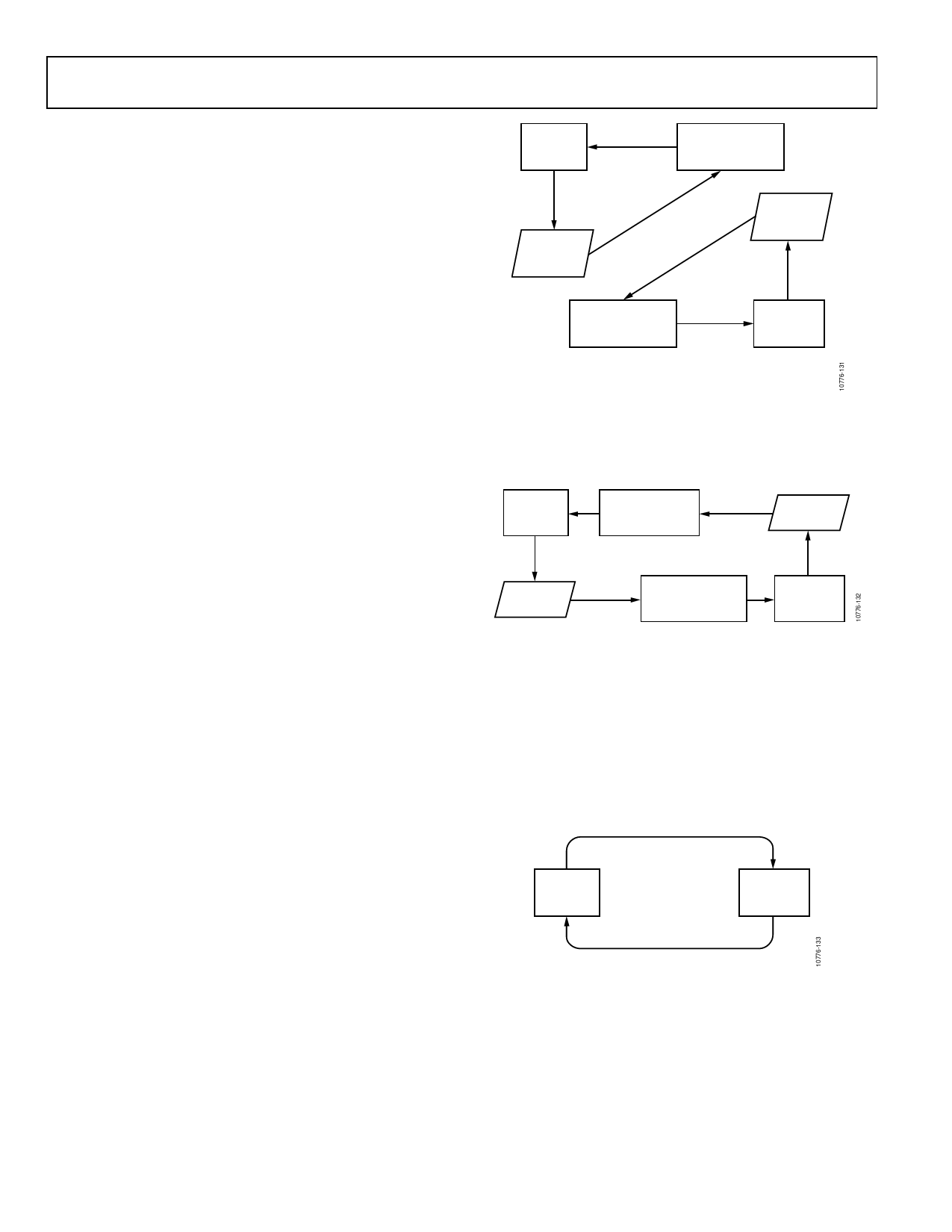
WAIT FOR
ACTIVITY
EVENT
WAIT FOR
PROCESSOR TO
CLEAR INTERRUPT
AWAKE = 1
ACTIVITY
INTERRUPT
TRIGGERS
WAIT FOR
PROCESSOR TO
CLEAR INTERRUPT
INACTIVITY
INTERRUPT
TRIGGERS
AWAKE = 1
WAIT FOR
INACTIVITY
EVENT
NOTES
1. THE AWAKE BIT DEFAULTS TO 1 WHEN ACTIVITY AND INACTIVITY
ARE NOT LINKED.
Figure 31. Flowchart Illustrating Activity and Inactivity Operation in Default Mode
In linked mode, each interrupt must be serviced by a host
processor before the next interrupt is enabled.
Linked mode operation is illustrated in the flowchart in Figure 32.
WAIT FOR
ACTIVITY
EVENT
WAIT FOR
PROCESSOR TO
CLEAR INTERRUP
AWAKE = 0 INACTIVITY
INTERRUPT
ACTIVITY
INTERRUPT
AWAKE = 1
WAIT FOR
PROCESSOR TO
CLEAR INTERRUPT
WAIT FOR
INACTIVITY
EVENT
Figure 32. Flowchart Illustrating Activity and Inactivity Operation in Linked Mode
Loop Mode
In loop mode, motion detection operates as described in the
Linked Mode section, but interrupts do not need to be serviced
by a host processor. This configuration simplifies the implemen-
tation of commonly used motion detection and enhances power
savings by reducing the amount of power used in bus communi-
cation.
Loop mode operation is illustrated in the flowchart in Figure 33.
AWAKE = 1
WAIT FOR
ACTIVITY
EVENT
WAIT FOR
INACTIVITY
EVENT
AWAKE = 0
Figure 33. Flowchart Illustrating Activity and Inactivity Operation in Loop Mode
Autosleep
When in linked or loop mode, enabling autosleep causes the
device to enter wake-up mode autonomously (see the Wake-Up
Mode section) when inactivity is detected, and to reenter
measurement mode when activity is detected.
The autosleep configuration is active only if linked or loop modes
are enabled. In the default mode, the autosleep setting is ignored.
Rev. E | Page 16 of 43
Share Link: 