MEW1000 Просмотр технического описания (PDF) - Unspecified
Номер в каталоге
Компоненты Описание
производитель
MEW1000 Datasheet PDF : 8 Pages
| |||
MEW1000 Series
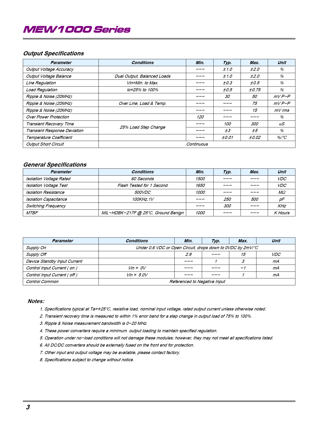
Output Specifications
Parameter
Output Voltage Accuracy
Output Voltage Balance
Line Regulation
Load Regulation
Ripple & Noise (20MHz)
Ripple & Noise (20MHz)
Ripple & Noise (20MHz)
Over Power Protection
Transient Recovery Time
Transient Response Deviation
Temperature Coefficient
Output Short Circuit
Conditions
Dual Output, Balanced Loads
Vin=Min. to Max.
Io=25% to 100%
Over Line, Load & Temp.
25% Load Step Change
Min.
---
---
---
---
---
---
---
120
---
---
---
Continuous
Typ.
{1.0
{1.0
{0.3
{0.5
30
---
---
---
100
{3
{0.01
Max.
{2.0
{2.0
{0.5
{0.75
50
75
15
---
300
{5
{0.02
Unit
%
%
%
%
mV P-P
mV P-P
mV rms
%
uS
%
%/]
General Specifications
Parameter
Conditions
Min.
Typ.
Max.
Unit
Isolation Voltage Rated
60 Seconds
1500
---
---
VDC
Isolation Voltage Test
Flash Tested for 1 Second
1650
---
---
VDC
Isolation Resistance
500VDC
1000
---
---
M[
Isolation Capacitance
100KHz,1V
---
250
500
pF
Switching Frequency
---
300
---
KHz
MTBF
MIL-HDBK-217F @ 25], Ground Benign
1000
---
---
K Hours
Remote On/Off Control
Parameter
Supply On
Supply Off
Device Standby Input Current
Control Input Current ( on )
Control Input Current ( off )
Control Common
Conditions
Min.
Typ.
Max.
Unit
Under 0.6 VDC or Open Circuit, drops down to 0VDC by 2mV/]
2.9
---
15
VDC
---
1
3
mA
Vin = 0V
---
---
-1
mA
Vin = 5.0V
---
---
1
mA
Referenced to Negative Input
Notes:
1. Specifications typical at Ta=+25], resistive load, nominal input voltage, rated output current unless otherwise noted.
2. Transient recovery time is measured to within 1% error band for a step change in output load of 75% to 100%.
3. Ripple & Noise measurement bandwidth is 0-20 MHz.
4. These power converters require a minimum output loading to maintain specified regulation.
5. Operation under no-load conditions will not damage these modules; however, they may not meet all specifications listed.
6. All DC/DC converters should be externally fused on the front end for protection.
7. Other input and output voltage may be available, please contact factory.
8. Specifications subject to change without notice.
3
MINMAX
REV:3 2008/10/02
Share Link: 