PCF2114 Просмотр технического описания (PDF) - Philips Electronics
Номер в каталоге
Компоненты Описание
производитель
PCF2114 Datasheet PDF : 64 Pages
| |||
Philips Semiconductors
LCD controller/drivers
Product specification
PCF2116 family
8.18 Programming MUX 1 : 32 displays with the
PCF2114x
To drive a 2-line by 24 characters MUX 1 : 32 display, use
instruction ‘Function set’ M, N to 0, 1. Note that the right
half of the display needs mirrored column connection
compared to a display driven by a PCF2116x.
To drive a 4-line by 12 characters MUX 1 : 32 display the
PCF2116x operating instructions apply. There is no
functional difference between the PCF2114x and the
PCF2116x in this mode. For such an application
set M, N to 1, 1 with the ‘Function set’ instruction.
8.19 Reset function
The PCF2116 automatically initializes (resets) when
power is turned on. After reset the chip has the following
state.
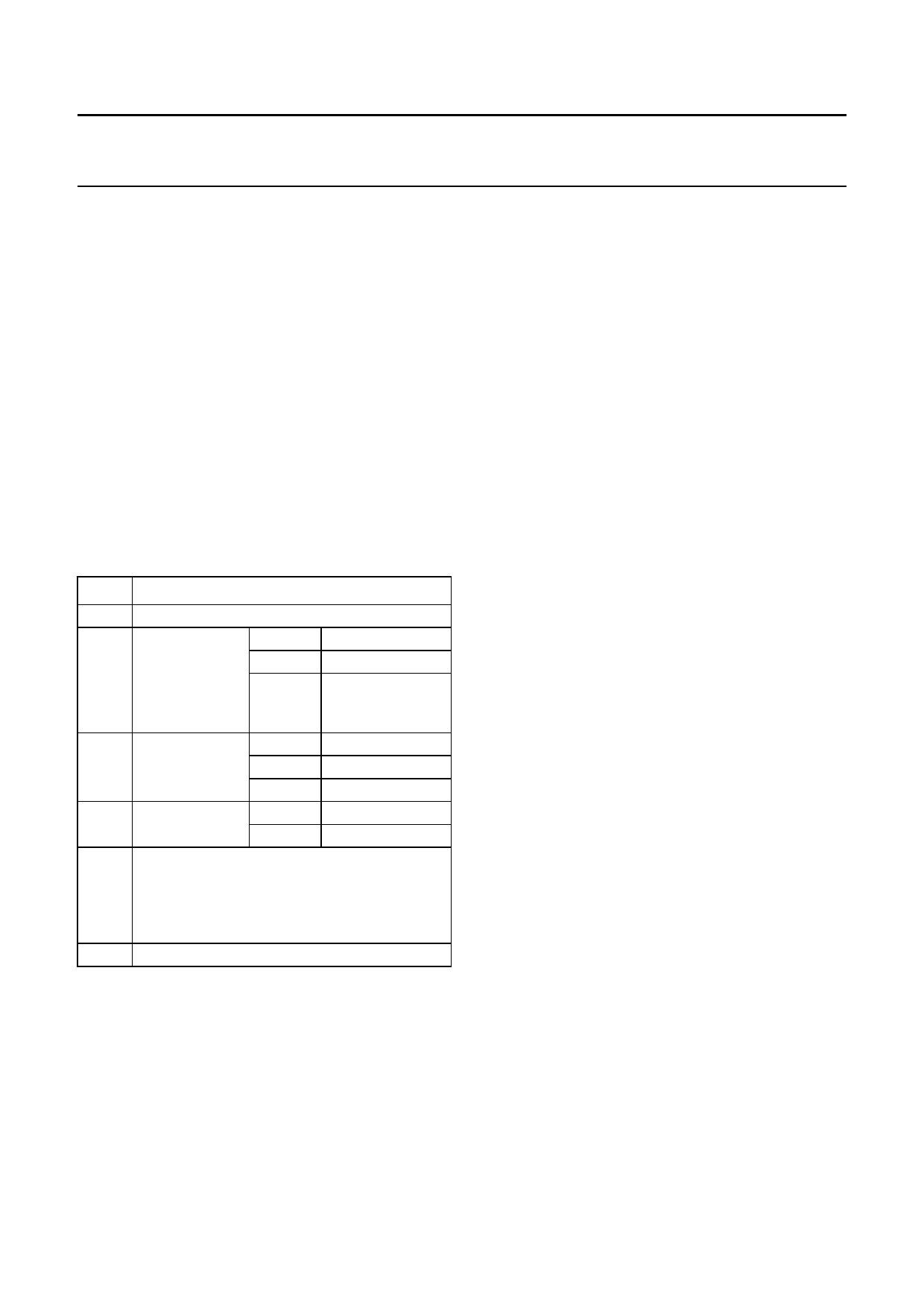
Table 2 State after reset
STEP
DESCRIPTION
1 display clear
2 function set
DL = 1 8-bit interface
M, N = 0 1-line display
G=0
3 display on/off D = 0
control
C=0
voltage
generator;
VLCD = V0
display off
cursor off
B = 0 blink off
4 entry mode set I/D = 1 +1 (increment)
S = 0 no shift
5 Default address pointer to DDRAM. The Busy
Flag (BF) indicates the busy state (BF = logic 1)
until initialization ends. The busy state lasts
2 ms. The chip may also be initialized by
software. See Figs 28 and 29.
6 I2C-bus interface reset
9 INSTRUCTIONS
Only two PCF2116 registers, the Instruction Register (IR)
and the Data Register (DR) can be directly controlled by
the microcontroller. Before internal operation, control
information is stored temporarily in these registers to allow
interface to various types of microcontrollers which
operate at different speeds or to allow interface to
peripheral control ICs.
The PCF2116 operation is controlled by the instructions
shown in Table 3 together with their execution time.
Details are explained in subsequent sections.
Instructions are of 4 categories, those that:
1. Designate PCF2116 functions such as display format,
data length, etc.
2. Set internal RAM addresses
3. Perform data transfer with internal RAM
4. Others.
In normal use, category 3 instructions are used most
frequently. However, automatic incrementing by 1 (or
decrementing by 1) of internal RAM addresses after each
data write lessens the microcontroller program load. The
display shift in particular can be performed concurrently
with display data write, enabling the designer to develop
systems in minimum time with maximum programming
efficiency.
During internal operation, no instruction other than
‘Read busy flag and address’ will be executed.
Because the Busy Flag is set to logic 1 while an instruction
is being executed, check to make sure it is on logic 0
before sending the next instruction or wait for the
maximum instruction execution time, as given in Table 3.
An instruction sent while the Busy Flag is HIGH will not be
executed.
1997 Apr 07
22
Share Link: 