MAX691AD Просмотр технического описания (PDF) - Maxim Integrated
Номер в каталоге
Компоненты Описание
производитель
MAX691AD Datasheet PDF : 16 Pages
| |||
Microprocessor Supervisory Circuits
Rp*
VOUT
CE IN
CE OUT
MAX691A
MAX693A
MAX800L
MAX800M
GND
CE
RAM 1
CE
CE
RAM 2
CE
CE
CE
RAM 3
CE
RAM 4
CE
*MAXIMUM Rp VALUE DEPENDS ON
THE NUMBER OF RAMS.
MINIMUM Rp VALUE IS 1kΩ.
ACTIVE-HIGH
CE LINES
FROM LOGIC
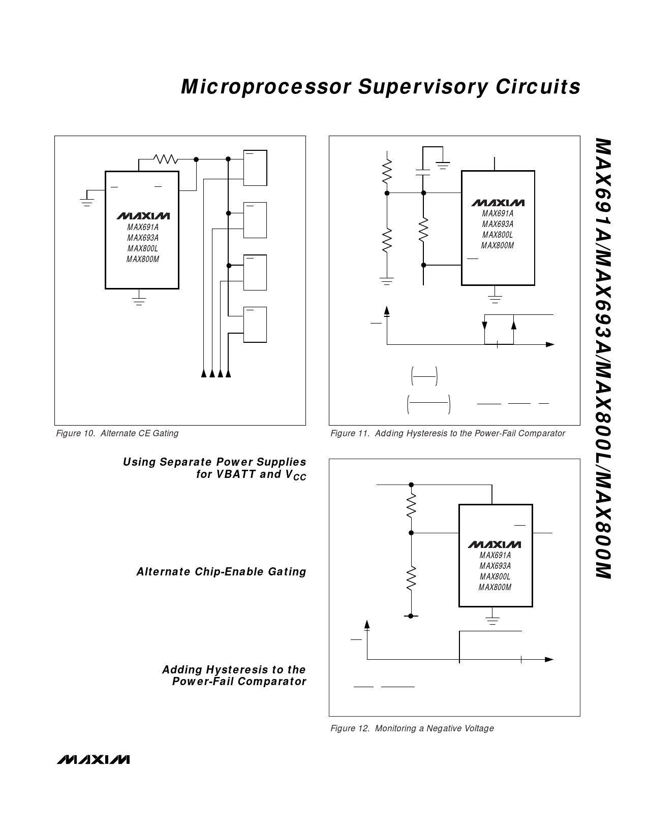
Figure 10. Alternate CE Gating
Using Separate Power Supplies
for VBATT and VCC
If using separate power supplies for VCC and VBATT,
VBATT must be less than 0.3V above VCC when VCC is
above the reset threshold. As described in the previ-
ous section, if VBATT exceeds this limit and power is
lost at VCC, current flows continuously from VBATT to
VCC via the VBATT-to-VOUT diode and the VOUT-to-VCC
switch until the circuit is broken (Figure 8).
Alternate Chip-Enable Gating
Using memory devices with both CE and CE inputs
allows the CE loop to be bypassed. To do this, con-
nect CE
connect
I–CNEtoOgUrToutnod,thpeulCl EupinCpEutOoUf TeatochVOmUeT,maonrdy
device (Figure 10). The CE input of each part then
connects directly to the chip-select logic, which does
not have to be gated.
Adding Hysteresis to the
Power-Fail Comparator
Hysteresis adds a noise margin to the power-fail com-
parator and prevents repeated triggering of PFO when
VIN is near the power-fail comparator trip point. Figure
11 shows how to add hysteresis to the power-fail com-
VIN
R1
C1*
R3
R2
TO µP
5V
PFO
0V
0V
VTRIP = 1.25
R1 + R2
R2
VH = 1.25/
R2 I I R3
R1 + R2 I I R3
+5V
VCC
PFI
MAX691A
MAX693A
MAX800L
MAX800M
PFO
GND
*OPTIONAL
VL VTRIP VH
VIN
VL
- 1.25
R1
+
5
- 1.25
R3
=
1.25
R2
Figure 11. Adding Hysteresis to the Power-Fail Comparator
+5V
R1
VCC
PFI
PFO
MAX691A
MAX693A
R2
MAX800L
MAX800M
GND
V-
5V
PFO
0V
VTRIP
0V
V-
5
- 1.25
R1
=
1.25
- VTRIP
R2
NOTE: VTRIP IS NEGATIVE
Figure 12. Monitoring a Negative Voltage
______________________________________________________________________________________ 13
Share Link: 