BA6901F Просмотр технического описания (PDF) - ROHM Semiconductor
Номер в каталоге
Компоненты Описание
производитель
BA6901F Datasheet PDF : 21 Pages
| |||
BA6901F
Datasheet
●Power dissipation
Power dissipation (total loss) indicates the power that can be consumed by IC at Ta = 25ºC (normal temperature). IC is
heated when it consumes power, and the temperature of IC chip becomes higher than ambient temperature. The
temperature that can be accepted by IC chip depends on circuit configuration, manufacturing process, etc, and consumable
power is limited. Power dissipation is determined by the temperature allowed in IC chip (maximum junction temperature)
and thermal resistance of package (heat dissipation capability). The maximum junction temperature is in general equal to
the maximum value in the storage temperature range.
Heat generated by consumed power of IC is radiated from the mold resin or lead frame of package. The parameter which
indicates this heat dissipation capability (hardness of heat release) is called heat resistance, represented by the symbol θ
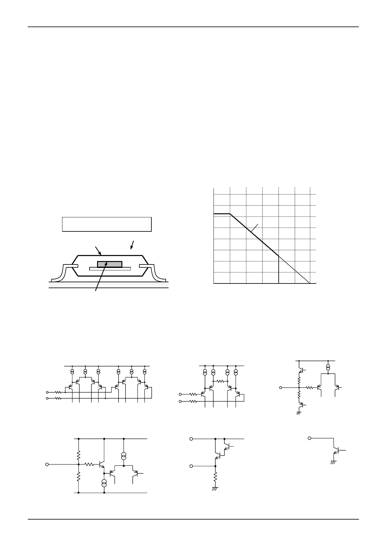
ja [℃/W]. The temperature of IC inside the package can be estimated by this heat resistance. Fig.19 shows the model of
heat resistance of the package.
Heat resistance θja, ambient temperature Ta, junction temperature Tj, and power consumption P can be calculated by the
equation below:
θja = (Tj – Ta) / P [°C/W]
Thermal derating curve indicates power that can be consumed by IC with reference to ambient temperature. Power that can
be consumed by IC begins to attenuate at certain ambient temperature. This gradient is determined by thermal resistance
θja.
Thermal resistance θja depends on chip size, power consumption, package ambient temperature, packaging condition,
wind velocity, etc., even when the same package is used. Thermal derating curve indicates a reference value measured at
a specified condition. Fig.20 shows a thermal derating curve (Value when mounting FR4 glass epoxy board 70 [mm] x 70
[mm] x 1.6 [mm] (copper foil area below 3 [%]))
Pd(mW)
800
700
625
600
θja = (Tj – Ta) / P [°C/W]
560
500
Ambient temperature Ta[°C]
400
Package surface temperature Tc[°C]
300
200
BA6901F
100
Chip surface temperature Tj[°C]
Power consumption P[W]
Fig.19 Thermal resistance
0
25 50 75 95 100 125 150 Ta(℃)
*Reduce by 5.0mW/°C over 25°C
(On 70.0mm x 70.0mm x 1.6mm glass epoxy board)
Fig.20 Thermal de-rating curve
●I/O equivalence circuit(Resistance values are typical)
1) Hall input terminal
2) Current limiting input terminal
Output current detecting terminal
Vcc
Vcc
3) Charge-discharge pulse
output terminal
Vcc
1kΩ
H+ 1kΩ
H-
1kΩ
CS
1kΩ
CL
TOUT
30Ω
30Ω
1kΩ
4) PWM input terminal
Vcc
PWM
30kΩ
100kΩ
1kΩ
GND
5) Output terminal
Vcc
A1, A2
15kΩ
6) Signal output terminal
FG、AL、ALB
www.rohm.com
© 2012 ROHM Co., Ltd. All rights reserved.
TSZ22111・15・001
13/17
TSZ02201-0H1H0B100500-1-2
18.DEC.2012 Rev.002
Share Link: 