VNH3ASP30-E Просмотр технического описания (PDF) - STMicroelectronics
Номер в каталоге
Компоненты Описание
производитель
VNH3ASP30-E Datasheet PDF : 34 Pages
| |||
VNH3ASP30-E
Application information
3.1
Reverse battery protection
Three possible solutions can be considered:
a Schottky diode D connected to VCC pin
an N-channel MOSFET connected to the GND pin (see Figure 32: Typical application circuit
for DC to 20 kHz PWM operation short circuit protection on page 20)
a P-channel MOSFET connected to the VCC pin
The device sustains no more than -30 A in reverse battery conditions because of the two
body diodes of the power MOSFETs. Additionally, in reverse battery condition the I/Os of
Root part number 1 are pulled down to the VCC line (approximately -1.5 V). A series resistor
must be inserted to limit the current sunk from the microcontroller I/Os. If IRmax is the
maximum target reverse current through µC I/Os, the series resistor is:
R = V-----I--O-I--R--s---m-–----a-V---x-C-----C--
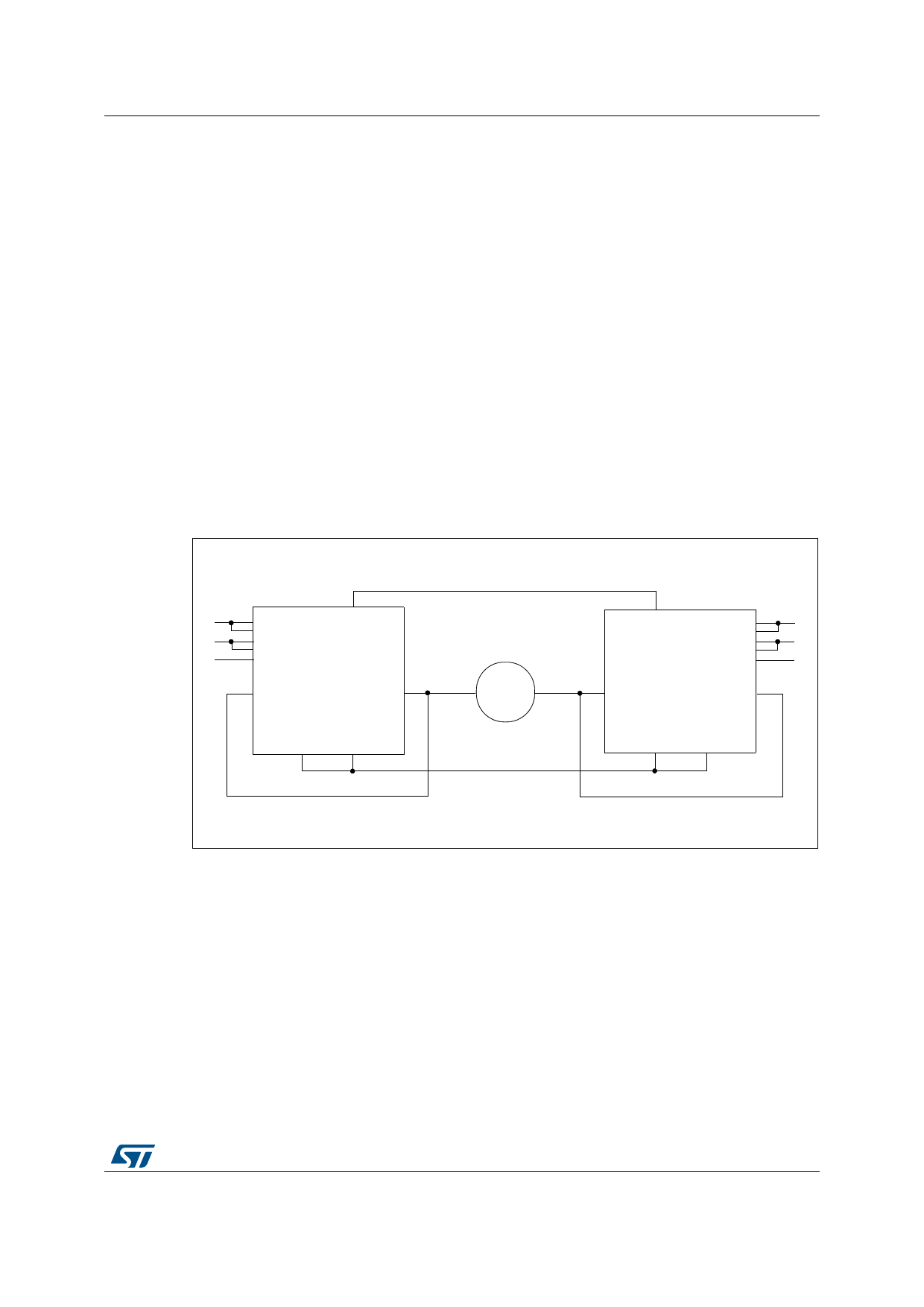
Figure 33. Half-bridge configuration
IDIPDNNWIIAABAMGGBA//EENNBA
OUTA
OUTB
GNDA GNDB
VCC
M
OUTA
DDIIAAGGABP//EEWIINNNNMABBA
OUTB
GNDA GNDB
Note:
The VNH3ASP30-E can be used as a high power half-bridge driver achieving an On
resistance per leg of 21 m.
DocID10833 Rev 7
21/34
34
Share Link: 