NCP432B(2016) Просмотр технического описания (PDF) - ON Semiconductor
Номер в каталоге
Компоненты Описание
производитель
NCP432B Datasheet PDF : 17 Pages
| |||
NCP431A, SC431A, NCP431B, SC431B, NCP432B, SC432B Series
NCP431/NCP432 OPEN−LOOP VOLTAGE GAIN
VERSUS FREQUENCY
NCP431/NCP432 OPEN−LOOP BODE PLOT WITH
LOAD CAP
Figure 34. Example 1 Circuit Open Loop Gain Plot
Example 2.
IC = 7.5 mA, RL = 2.2 kW, CL = 0.01 mF. Cathode tied to
reference input pin. An examination of the data sheet
stability boundary curve (Figure 18) shows that this value of
load capacitance and cathode current is on the boundary.
Define the transfer gain.
The DC gain is:
G + GMRGMGoRL + (2.138)(1.0M)(1.25m)(230)
+ 6389 + 76 dB
The resulting open loop Bode plot is shown in Figure 35.
The asymptotic plot may be expressed as the following
equation:
ǒ Ǔ jf
1)
500 kHz
ǒ Ǔǒ Ǔǒ Ǔ Av + 615
1 ) jf
1 ) jf
1 ) jf
8.0 kHz
60 kHz
7.2 kHz
Note that the transfer function now has an extra pole
formed by the load capacitance and load resistance.
Note that the crossover frequency in this case is about
250 kHz, having a phase margin of about −46°. Therefore,
instability of this circuit is likely.
Figure 35. Example 2 Circuit Open Loop Gain Plot
With three poles, this system is unstable. The only hope
for stabilizing this circuit is to add a zero. However, that can
only be done by adding a series resistance to the output
capacitance, which will reduce its effectiveness as a noise
filter. Therefore, practically, in reference voltage
applications, the best solution appears to be to use a smaller
value of capacitance in low noise applications or a very large
value to provide noise filtering and a dominant pole rolloff
of the system.
The NCP431/NCP432 is often used as a regulator in
secondary side of a switch mode power supply (SMPS).
The benefit of this reference is high and stable gain under
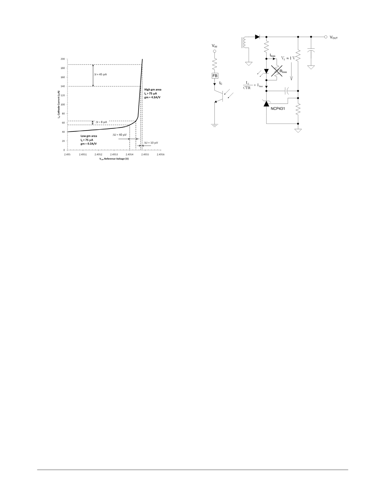
low bias currents. Figure 36 shows dependence of the gain
(dynamic impedance) on the bias current. Value of
minimum cathode current that is needed to assure stable gain
is 80 mA maximum.
www.onsemi.com
12
Share Link: 