MAX9205EAI/V Просмотр технического описания (PDF) - Maxim Integrated
Номер в каталоге
Компоненты Описание
производитель
MAX9205EAI/V Datasheet PDF : 13 Pages
| |||
MAX9205/MAX9207
10-Bit Bus LVDS Serializers
AC ELECTRICAL CHARACTERISTICS (continued)
(VAVCC = VDVCC = +3.0V to +3.6V, RL = 27Ω ±1% or 50Ω ±1%, CL = 10pF, TA = -40°C to +85°C. Typical values are at VAVCC =
VDVCC = +3.3V and TA = +25°C, unless otherwise noted.) (Notes 3, 5)
PARAMETER
SYMBOL
CONDITIONS
MIN TYP MAX UNITS
Deterministic Jitter (Figure 9)
tDJIT
MAX9205
MAX9207
16MH z
40MH z
40MH z
66MH z
200
140
ps
140 (pk-pk)
140
Random Jitter (Figure 10)
tRJIT
MAX9205
MAX9207
16MH z
40MH z
40MH z
66MH z
13
9
ps
9 (RMS)
6
Note 2: Current into a pin is defined as positive. Current out of a pin is defined as negative. All voltages are referenced to ground
except VOD, ∆VOD, and VOS.
Note 3: CL includes scope probe and test jig capacitance.
Note 4: Parameters 100% tested at TA = +25°C. Limits over operating temperature range guaranteed by design and characterization.
Note 5: AC parameters are guaranteed by design and characterization.
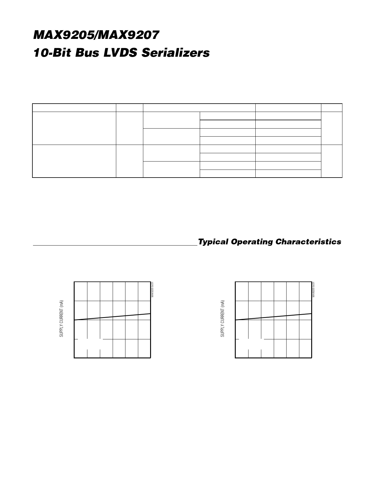
Typical Operating Characteristics
(VAVCC = VDVCC = +3.3V, RL = 27Ω, CL = 10pF, TA = +25°C, unless otherwise noted.)
WORST-CASE PATTERN SUPPLY CURRENT
vs. SUPPLY VOLTAGE
50
WORST-CASE PATTERN SUPPLY CURRENT
vs. SUPPLY VOLTAGE
50
40
40
30
30
20
TCLK = 40MHz
MAX9205
10
3.0
3.3
3.6
SUPPLY VOLTAGE (V)
20
TCLK = 40MHz
MAX9205
10
3.0
3.3
3.6
SUPPLY VOLTAGE (V)
4
Maxim Integrated
Share Link: 