MAX6653 Просмотр технического описания (PDF) - Maxim Integrated
Номер в каталоге
Компоненты Описание
производитель
MAX6653 Datasheet PDF : 24 Pages
| |||
Temperature Monitors and
PWM Fan Controllers
Register Summary (continued)
Addr(H)
3D
3E
3F
READ/WRITE POR STATE
DESCRIPTION
R
0011 1000 Device ID
R
0100 1101 Manufacturer ID
THERM behavior/revision:
Bit [7]: THERM behavior:
R/W
1000 0000
1: enable THERM as an output.
0: disable THERM as an output.
Bits [3:0] revision number.
*For MAX6663 bit 7 has to be 1 all the time.
PC Board Layout
Follow these guidelines to reduce the measurement
error of the temperature sensors:
1) Place the MAX6653/MAX6663/MAX6664 as close
as is practical to the remote diode. In noisy environ-
ments, such as a computer motherboard, this dis-
tance can be 4in to 8in (typ). This length can be
increased if the worst noise sources are avoided.
Noise sources include CRTs, clock generators,
memory buses, and ISA/PCI buses.
2) Do not route the DXP-DXN lines next to the deflec-
tion coils of a CRT. Also, do not route the traces
across fast digital signals, which can easily intro-
duce 30°C error, even with good filtering.
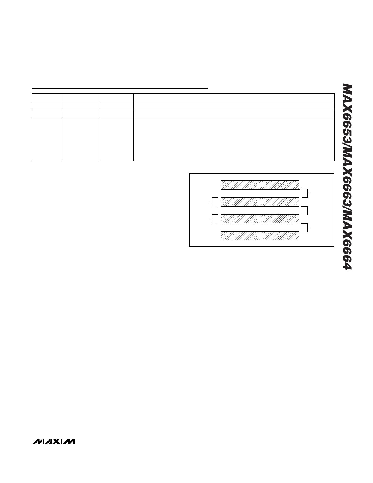
3) Route the DXP and DXN traces in parallel and in
close proximity to each other, away from any higher
voltage traces, such as 12VDC. Leakage currents
from PC board contamination must be dealt with
carefully since a 20MΩ leakage path from DXP to
ground causes about 1°C error. If high-voltage
traces are unavoidable, connect guard traces to
GND on either side of the DXP-DXN traces (Figure
6).
4) The 10-mil widths and spacing recommended in
Figure 6 are not absolutely necessary, as they offer
only a minor improvement in leakage and noise over
narrow traces. Use wider traces when practical.
5) Add a 200Ω resistor in series with VCC for best
noise filtering (see Typical Operating Circuits).
Twisted-Pair and Shielded Cables
Use a twisted-pair cable to connect the remote sensor
for remote-sensor distances longer than 8in, or in very
noisy environments. Twisted-pair cable lengths can be
between 6ft and 12ft before noise introduces excessive
errors. For longer distances, the best solution is a
shielded twisted pair like that used for audio micro-
phones. For example, Belden 8451 works well for dis-
10 MILS
10 MILS
GND
10 MILS
DXP
MINIMUM
DXN
10 MILS
GND
Figure 6. Recommended DXP/DXN PC Traces
tances up to 100ft in a noisy environment. At the
device, connect the twisted pair to DXP and DXN and
the shield to GND. Leave the shield unconnected at the
remote sensor. For very long cable runs, the cable’s
parasitic capacitance often provides noise filtering, so
the 2200pF capacitor can often be removed or reduced
in value.
Cable resistance also affects remote-sensor accuracy.
For every 1Ω of series resistance, the error is approxi-
mately 0.5°C.
PC Board Layout Checklist
• Place the MAX6653/MAX6663/MAX6664 close to
the remote-sense junction.
• Keep traces away from high voltages (+12V bus).
• Keep traces away from fast data buses and CRTs.
• Use recommended trace widths and spacings.
• Place a ground plane under the traces.
• Use guard traces flanking DXP and DXN and con-
necting to GND.
• Place the noise filter and the 0.1µF VCC bypass
capacitors close to the MAX6653/MAX6663/
MAX6664.
______________________________________________________________________________________ 19
Share Link: 