LCX027AK Просмотр технического описания (PDF) - Sony Semiconductor
Номер в каталоге
Компоненты Описание
производитель
LCX027AK Datasheet PDF : 23 Pages
| |||
LCX027AK
2. LCD Panel Operations
• A vertical driver, which consists of vertical shift registers, enable-gates and buffers, applies a selected pulse
to every 225 gate lines sequentially in every horizontal scanning period. A vertical shift register scans the
gate lines from the top to bottom of the panel.
• The selected pulse is delivered when the enable pin turns to High level. PAL mode images are displayed by
controlling the enable and VCK pin. The enable pin should be High when not in use.
• A horizontal driver, which consists of horizontal shift registers, gates and CMOS sample-and-hold circuits
applies selected pulses to every 800 signal electrodes sequentially in a single horizontal scanning period.
• Scanning direction of horizontal shift register can be switched with RGT pin. Scanning direction is left to right
for RGT pin at High level; and right to left for RGT pin at Low level. (These scanning directions are from a
front view.) Normally, set to High level.
• Vertical and horizontal drivers address one pixel and then turn on Thin Film Transistors (TFTs; two TFTs) to
apply a video signal to the dot. The same procedures lead to the entire 225 × 800 dots to display a picture in
a single vertical scanning period.
• Pixel dots are arranged in a delta pattern, where sets of RGB pixels are positioned with 1.5-dot shifted
against adjacent horizontal line. 1.5-dot shift of a horizontal driver output pulse against horizontal
synchronized signal is required to apply a video signal to each dot properly. 1H reversed displaying mode is
required to apply video signal to the panel.
• The video signal shall be input with polarity-inverted system in every horizontal cycle.
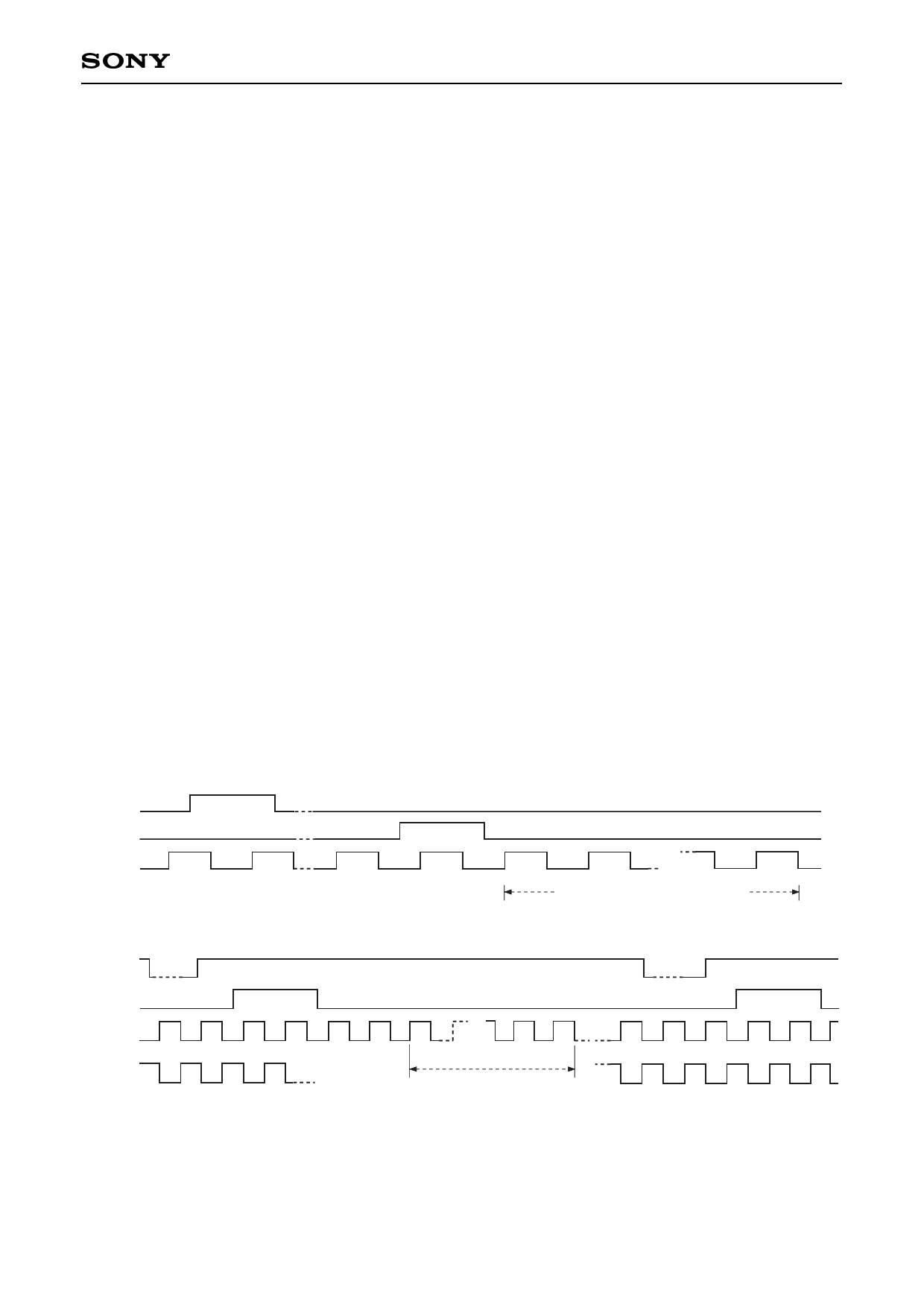
• Timing diagrams of the vertical and the horizontal right-direction scanning (RGT = High level) display cycle
are shown below.
HCK1 and HCK2 should be inverted to display the left-direction horizontal scanning (RGT = Low level).
This inversion enables the center of the image to be fixed by eliminating offsets. (When an example of
system mentioned on this data sheet is used, TG performs this operation automatically.)
(1) Vertical display cycle
VD
VST
VCK
(2) Horizontal display cycle (right scan)
1
2
224 225
Vertical display cycle 225H (14.3ms)
BLK
HST
HCK1
HCK2
123 45 6
270
271
Horizontal display cycle (48.4µs)
The horizontal display cycle consists of 800/3 = 267 clock pulses because of RGB simultaneous sampling.
∗ Refer to Description of Operation "3. RGB Simultaneous Sampling."
– 17 –
Share Link: 