MAX888ECJ(1999) Просмотр технического описания (PDF) - Maxim Integrated
Номер в каталоге
Компоненты Описание
производитель
MAX888ECJ Datasheet PDF : 20 Pages
| |||
Wireless and Satellite Handset
Power-Management ICs
For example:
VREF = 1.25V
VTHF = falling threshold = 2.52V
VHYS = hysteresis = 0.1V
VTHR = rising threshold = VTHF + VHYS = 2.62V
R1 = 619kΩ (1%)
R2 = 562kΩ (1%)
R3 = 47.6kΩ (1%)
Power-On Sequence
(Including RESET and Start-Up Timers)
Drive ON low to begin the power-up sequence. To reduce
overall system cost and complexity, the MAX886/MAX888
incorporate RESET and start-up timers with the power-on
sequence.
The MAX886/MAX888 turn on the reference when ON
goes low. Once the reference is fully powered up, if the
input voltage exceeds the internal undervoltage-lockout
threshold (UVLOR), Regulator 0 turns on. Once OUT0
is in regulation, OUT2 and OUT4 turn on. Once OUT2 is
in regulation, OUT1 and OUT5 turn on and the 75ms
reset timer begins. RESET remains low from the time
OUT2 is valid until the reset timer times out. After the
reset period expires, a 50ms start-up timer begins. The
MAX886/MAX888 shut down if the external logic or con-
troller fails to drive OFF high before the start-up timer
expires. Drive OFF high to continue operation. Driving
OFF low turns off the IC.
There is no required sequence to power off any regula-
tor after the device has turned on. Regulators can be
powered off selectively by sending the correct code
through the serial interface (Table 1).
MAX886
OUT2
MAX888
10k
RESET
ON
ONSTAT
µC
OFF
Figure 4. One-Button On/Off Control with ONSTAT
ONSTAT Output
ONSTAT is a logic output that follows ON. Connect
ONSTAT to the external logic or controller to sense
when the ON pin has been brought low to request shut-
down. This allows easy implementation of a one-button
on/off control scheme (Figure 4).
Thermal Overload Protection
An internal thermal sensor shuts the MAX886/MAX888
down when the maximum temperature limit is exceeded
(160°C typical).
I2C-Compatible Serial Interface
Use an I2C-compatible serial interface to turn the
MAX886/MAX888 on and off, as well as control each
regulator’s output voltage and program the DC-DC
converter and charge pump’s oscillator frequency. Use
standard I2C-compatible receive-byte commands to
program the IC. This part is always a slave to the bus
master. The chip address is 1001 111.
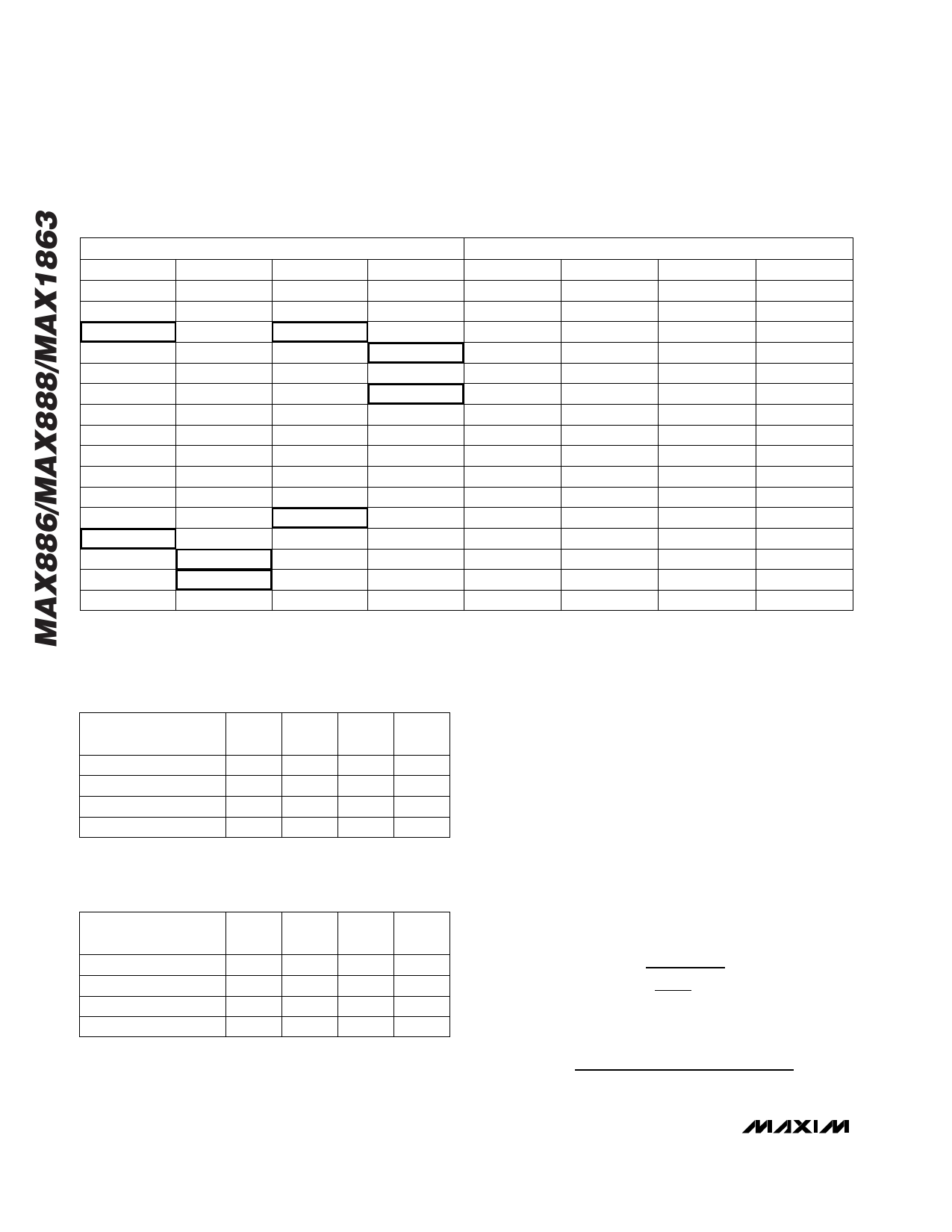
POR State
The power-on reset state of all the DAC and frequency
registers is 0Fh, except for DAC1 which is 04h. The
power-on reset state of the ONX bits is 1 (Table 1). The
power-on voltage for each regulator is shown in bold in
Tables 2, 3, and 5.
Applications Information
Inductor Selection
The essential parameters for inductor selection are
inductance and current rating. The MAX886/MAX888
operate with a wide range of inductance values. In many
applications, values between 10µH and 68µH take best
advantage of the controller’s high switching frequency.
Calculate the minimum inductance value using the sim-
plified equation:
( ) ( ( ) ) L MIN
=
4 VBATT MAX − VOUT0
⋅ ⋅ IPEAK fOSC VBATT / VOUT0
where IPEAK is the peak inductor current (0.9A) and
fOSC is the switching frequency.
For example, for a 6V battery voltage, a desired VOUT0
is 3.3V, the oscillator frequency is 375kHz, and 15µH is
the minimum inductance required.
Diode Selection
The MAX886/MAX888’s high switching frequency
demands a high-speed rectifier. Schottky diodes, such
as the 1N5817–1N5822 family or surface-mount
MBR0520L series are recommended. Ultra-high-speed
rectifiers with reverse recovery times around 50ns or
16 ______________________________________________________________________________________
Share Link: 