R1211X Просмотр технического описания (PDF) - RICOH Co.,Ltd.
Номер в каталоге
Компоненты Описание
производитель
R1211X Datasheet PDF : 40 Pages
| |||
R1211x
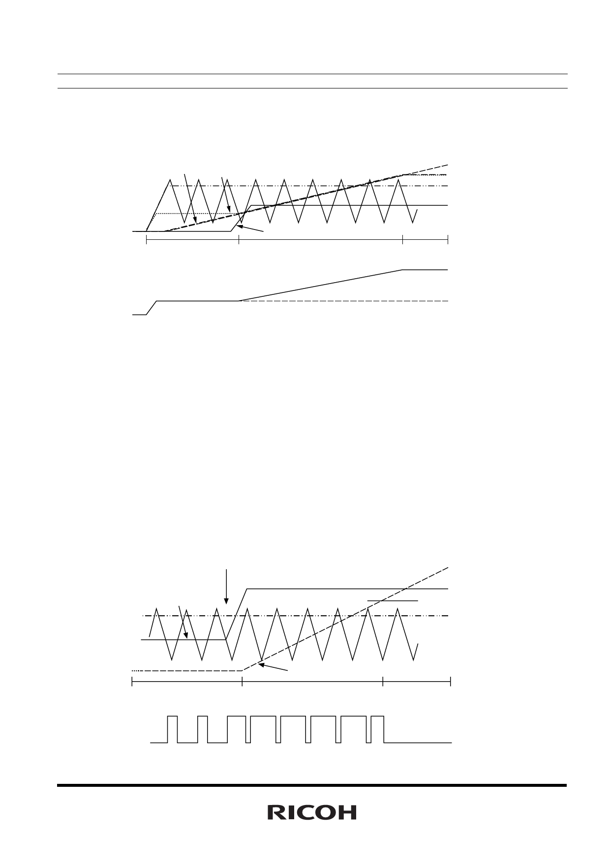
(Step3)
When SS reaches 1V, soft-start operation finishes. VREF becomes constant voltage (=1V). Then the switching
operation becomes normal mode.
SS,VREF VFB
SS
VFB,VREF
DTC
AMPOUT
Step1
AMPOUT
Step2
Step3
VOUT
VIN
<Latch Protection Operation>
The operation of Latch protection circuit is as follows: When AMPOUT becomes "H" and the IC detects
maximum duty cycle, charge to an external capacitor, C2 of DELAY pin starts. And maximum duty cycle
continues and the voltage of DELAY pin reaches delay voltage detector threshold, VDLY, outputs "L" to EXT pin
and turns off the external power MOSFET.
To release the latch protection operation, make the IC be standby mode with CE pin and make it active in
terms of R1211x002B/D version. Otherwise, make supply voltage down to UVLO detector threshold or lower,
and make it rise up to the normal input voltage.
During the soft-start time, if the duty cycle may be the maximum, protection circuit does not work and DELAY
pin is fixed at GND level.
The delay time of latch protection can be calculated with C2, VDLY, and Delay Pin Charge Current, IDLY1, as in
the next formula.
t=C2 × VDLY/IDLY1
Once after the maximum duty is detected and released before delay time, charge to the capacitor is halt and
delay pin outputs "L".
Output Short
AMPOUT
VDLY
AMPOUT
DTC
Normal
EXT
DELAY
Maxduty Operation
Latched
13
Share Link: 