TL431CDR2 Просмотр технического описания (PDF) - ON Semiconductor
Номер в каталоге
Компоненты Описание
производитель
TL431CDR2 Datasheet PDF : 19 Pages
| |||
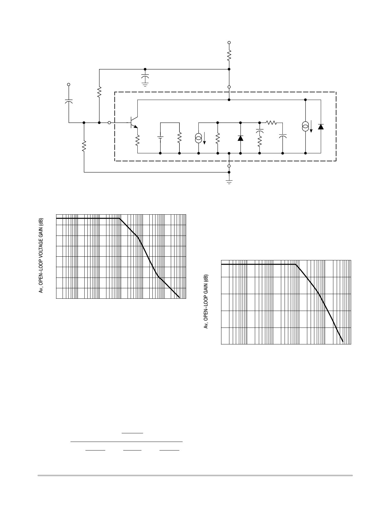
TL431, A, B Series, NCV431A, B
VCC
RL
Input
CL
15 k
9.0 mF
8.25 k
Ref
Vref
1
1.78 V
GM
+
Rref
500 k
−
16
3
Cathode
RGM
1.0 M
RP2
10 M
CP1
20 pF
RZ1
15.9 k
Go
1.0 mmho
CP2
0.265 pF
Anode 2
Figure 31. Simplified TL431 Device Model
TL431 OPEN−LOOP VOLTAGE GAIN VERSUS FREQUENCY
60
50
40
30
20
10
0
−10
−20
101
102
103
104
105
106
107
f, FREQUENCY (Hz)
Figure 32. Example 1 Circuit Open Loop Gain Plot
Example 2.
IC = 7.5 mA, RL = 2.2 kW, CL = 0.01 mF. Cathode tied to
reference input pin. An examination of the data sheet
stability boundary curve (Figure 15) shows that this value of
load capacitance and cathode current is on the boundary.
Define the transfer gain.
The DC gain is:
G + GMRGMGoRL +
(2.323)(1.0 M)(1.25 m)(2200) + 6389 + 76 dB
The resulting open loop Bode plot is shown in Figure 33.
The asymptotic plot may be expressed as the following
equation:
ǒ Ǔ 1
)
jf
500 kHz
ǒ Ǔǒ Ǔǒ Ǔ Av + 615
1
)
jf
8.0 kHz
1
)
60
jf
kHz
1
)
7.2
jf
kHz
Note that the transfer function now has an extra pole
formed by the load capacitance and load resistance.
Note that the crossover frequency in this case is about
250 kHz, having a phase margin of about −46 degrees.
Therefore, instability of this circuit is likely.
TL431 OPEN−LOOP BODE PLOT WITH LOAD CAP
80
60
40
20
0
−20
101
102
103
104
105
106
f, FREQUENCY (Hz)
Figure 33. Example 2 Circuit Open Loop Gain Plot
With three poles, this system is unstable. The only hope
for stabilizing this circuit is to add a zero. However, that can
only be done by adding a series resistance to the output
capacitance, which will reduce its effectiveness as a noise
filter. Therefore, practically, in reference voltage
applications, the best solution appears to be to use a smaller
value of capacitance in low noise applications or a very
large value to provide noise filtering and a dominant pole
rolloff of the system.
http://onsemi.com
12
Share Link: 