HI5800KCD(1999) Просмотр технического описания (PDF) - Intersil
Номер в каталоге
Компоненты Описание
производитель
HI5800KCD Datasheet PDF : 15 Pages
| |||
HI5800
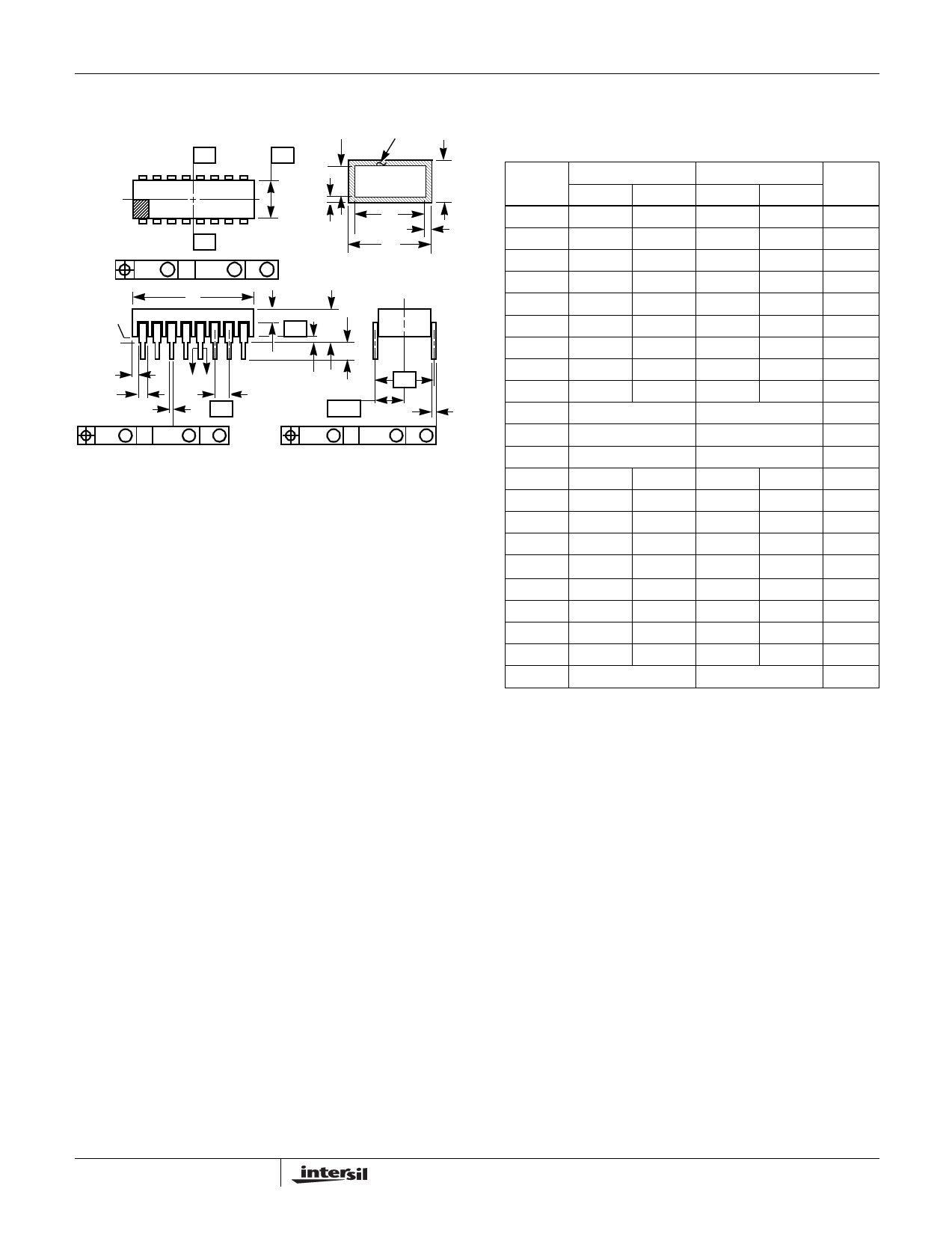
Ceramic Dual-In-Line Metal Seal Packages (SBDIP)
-A-
-D-
E
-B-
bbb S C A - B S D S
c1 LEAD FINISH
BASE
METAL
(c)
b1
M
M
(b)
SECTION A-A
D
BASE
PLANE
SEATING
PLANE
S1
b2
b
AA
e
ccc M C A - B S D S
S2
Q
-C- A
L
eA
eA/2
c
aaa M C A - B S D S
NOTES:
1. Index area: A notch or a pin one identification mark shall be locat-
ed adjacent to pin one and shall be located within the shaded
area shown. The manufacturer’s identification shall not be used
as a pin one identification mark.
2. The maximum limits of lead dimensions b and c or M shall be
measured at the centroid of the finished lead surfaces, when
solder dip or tin plate lead finish is applied.
3. Dimensions b1 and c1 apply to lead base metal only. Dimension
M applies to lead plating and finish thickness.
4. Corner leads (1, N, N/2, and N/2+1) may be configured with a
partial lead paddle. For this configuration dimension b3 replaces
dimension b2.
5. Dimension Q shall be measured from the seating plane to the
base plane.
6. Measure dimension S1 at all four corners.
7. Measure dimension S2 from the top of the ceramic body to the
nearest metallization or lead.
8. N is the maximum number of terminal positions.
9. Braze fillets shall be concave.
10. Dimensioning and tolerancing per ANSI Y14.5M - 1982.
11. Controlling dimension: INCH.
D40.6 MIL-STD-1835 CDIP2-T40 (D-5, CONFIGURATION C)
40 LEAD CERAMIC DUAL-IN-LINE METAL SEAL PACKAGE
INCHES
MILLIMETERS
SYMBOL MIN
MAX
MIN
MAX NOTES
A
-
0.225
-
5.72
-
b
0.014
0.026
0.36
0.66
2
b1
0.014
0.023
0.36
0.58
3
b2
0.045
0.065
1.14
1.65
-
b3
0.023
0.045
0.58
1.14
4
c
0.008
0.018
0.20
0.46
2
c1
0.008
0.015
0.20
0.38
3
D
-
2.096
-
53.24
4
E
0.510
0.620 12.95
15.75
4
e
0.100 BSC
2.54 BSC
-
eA
0.600 BSC
15.24 BSC
-
eA/2
0.300 BSC
7.62 BSC
-
L
0.125
0.200
3.18
5.08
-
Q
0.015
0.070
0.38
1.78
5
S1
0.005
-
0.13
-
6
S2
0.005
-
0.13
-
7
α
90o
105o
90o
105o
-
aaa
-
0.015
-
0.38
-
bbb
-
0.030
-
0.76
-
ccc
-
0.010
-
0.25
-
M
-
0.0015
-
0.038
2
N
40
40
8
Rev. 0 4/94
All Intersil semiconductor products are manufactured, assembled and tested under ISO9000 quality systems certification.
Intersil semiconductor products are sold by description only. Intersil Corporation reserves the right to make changes in circuit design and/or specifications at any time with-
out notice. Accordingly, the reader is cautioned to verify that data sheets are current before placing orders. Information furnished by Intersil is believed to be accurate and
reliable. However, no responsibility is assumed by Intersil or its subsidiaries for its use; nor for any infringements of patents or other rights of third parties which may result
from its use. No license is granted by implication or otherwise under any patent or patent rights of Intersil or its subsidiaries.
For information regarding Intersil Corporation and its products, see web site http://www.intersil.com
Sales Office Headquarters
NORTH AMERICA
Intersil Corporation
P. O. Box 883, Mail Stop 53-204
Melbourne, FL 32902
TEL: (321) 724-7000
FAX: (321) 724-7240
EUROPE
Intersil SA
Mercure Center
100, Rue de la Fusee
1130 Brussels, Belgium
TEL: (32) 2.724.2111
FAX: (32) 2.724.22.05
ASIA
Intersil (Taiwan) Ltd.
7F-6, No. 101 Fu Hsing North Road
Taipei, Taiwan
Republic of China
TEL: (886) 2 2716 9310
FAX: (886) 2 2715 3029
15
Share Link: 