P-1624BA-STA Просмотр технического описания (PDF) - HIROSE ELECTRIC
Номер в каталоге
Компоненты Описание
производитель
P-1624BA-STA Datasheet PDF : 31 Pages
| |||
The product information in this catalog is for reference only. Please request the Engineering Drawing for the most current and accurate design information.
All non-RoHS products have been discontinued, or will be discontinued soon. Please check the products status on the Hirose website RoHS search at www.hirose-connectors.com, or contact your Hirose sales representative.
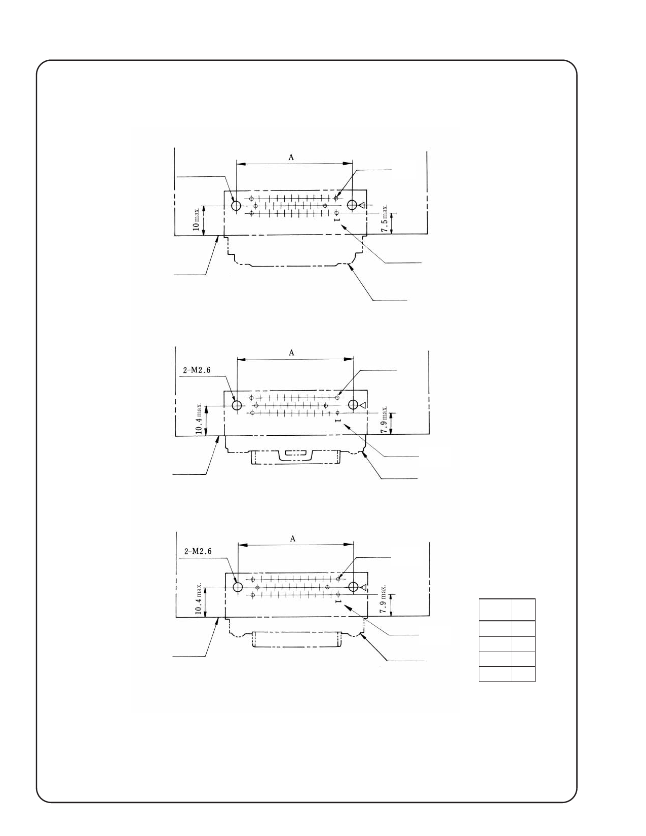
Recommended Mounting Pattern
For insertion-soldering in the PCB, drill mounting holes as shown in the figure below.
Unit: mm
2−M2.6 hole
Post hole
136
PCB End
Pin No.
Connector
With top-touch-lock type stopper bracket
PCB End
hole
PCB End
Pin No.
Connector
With side-lock type stopper bracket
hole
Post hole
PCB End
Connector Unit Type
Pin No.
Connector
No. of
pin
A
20
27
28
34
34
39
60
61
The triangle mark represents the position of the same
mark on the connector unit.
Above pattern is shown from view direction of the conec-
tor mounting side.
04/2009
Share Link: 